Shell structure of turbine shell

A shell structure, turbine shell technology, applied in engine components, machines/engines, internal combustion piston engines, etc., can solve problems such as the inability to achieve bypass and balance switching, achieve simple structure, low manufacturing and adjustment costs, slow down The effect of exhaust gas pulses

Pending Publication Date: 2018-02-27
WUXI CUMMINS TURBO TECH
View PDF1 Cites 4 Cited by
  • Summary
  • Abstract
  • Description
  • Claims
  • Application Information

AI Technical Summary

Problems solved by technology

And this technology can only realize the balance function, compared with the present invention, can not realize the switching of bypass and balance

Method used


Image

  • Shell structure of turbine shell
  • Shell structure of turbine shell
  • Shell structure of turbine shell

Examples


Embodiment Construction

[0021] The specific embodiments of the present invention will be further described below in conjunction with the accompanying drawings.

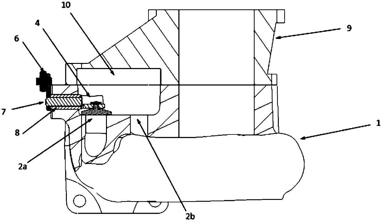
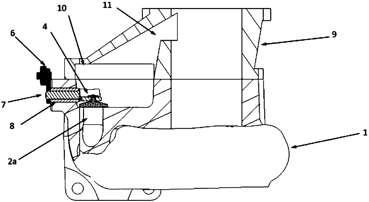
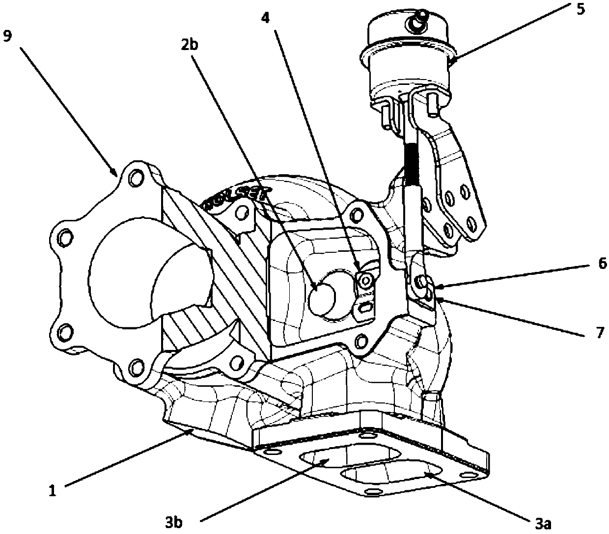
[0022] Figure 1~6 Among them, including the turbine casing 1, the first turbine casing wastegate passage 2a, the upper passage 2a-1, the lower passage 2a-2, the second turbine casing wastegate passage 2b, the first turbine casing intake flow passage 3a, the second Turbine casing inlet flow passage 3b, wastegate valve 4, pneumatic actuator 5, rocker arm 6, rocker shaft 7, bushing 8, transition joint 9, transition joint cavity 10, transition joint waste gate passage 11, etc.

[0023] Such as Figure 1~6 As shown, a turbine casing structure of the present invention includes a turbine casing 1, the outlet of the turbine casing 1 is sealed and connected to a transition joint 9, a transition joint cavity 10 is formed between the transition joint 9 and the turbine casing 1, and the upper part of the turbine casing 1 The first turbine casing wast...


PUM


Abstract

The invention belongs to the technical field of engine turbochargers, and relates to a shell structure of a turbine shell. The shell structure comprises the turbine shell; an outlet of the turbine shell is in sealed connection with a transition joint, and a transition joint cavity is formed between the transition joint and the turbine shell; a first turbine shell flue-gas bypass channel is formedin the upper part in the turbine shell, the gas inlet end of the first turbine shell flue-gas bypass channel communicates with a first turbine shell gas-inlet flowing channel formed in the bottom of the turbine shell, and the gas outlet end of the first turbine shell flue-gas bypass channel communicates with the transition joint cavity; and the turbine shell is internally provided with a flue-gasbypass valve for controlling opening and closing of the first turbine shell flue-gas bypass channel, and the bottom of the turbine shell is further provided with a second turbine shell gas-inlet flowing channel. According to the shell structure of the turbine shell, by adjusting the structures of the transition joint and the turbine shell, selecting and switching of the two structures are achieved, so that the overall combustion efficiency of an engine is improved, fuel economy is improved accordingly, and meanwhile, the risks of an excessive high supercharging pressure and an excessive high rotating speed of a supercharger are reduced.

Description

technical field [0001] The invention belongs to the technical field of engine turbochargers, and relates to a turbine casing shell structure. Background technique [0002] A turbocharger is actually an air compressor that compresses air to increase the air intake to the engine. It uses the inertial momentum of the exhaust gas discharged from the engine to drive the turbine in the turbine housing, and the turbine drives the coaxial impeller, which presses the air sent by the air filter pipe to pressurize it into the cylinder. When the engine speed increases, the exhaust gas discharge speed and the turbine speed also increase synchronously, and the impeller compresses more air into the cylinder, and the pressure and density of the air increase to burn more fuel. Increase the fuel volume and adjust the engine speed accordingly. , the output power of the engine can be increased. The design of the asymmetrical double flow channel is based on the exhaust gas recirculation techno...

Claims


Application Information

Patent Timeline
Patent Type & Authority Applications(China)
IPC IPC(8): F01D25/24F02B37/18
CPCF01D25/24F01D25/243F02B37/183F02B37/186F05D2220/40Y02T10/12
Inventor 汪博文袁家骐金建交
Owner WUXI CUMMINS TURBO TECH
Why Eureka
Try Eureka