Thruster ion beam current center line laser positioning device and method

A laser positioning and thruster technology, applied in active optical measurement devices, measurement devices, instruments, etc., to save space, improve positioning accuracy, and ensure consistency

Inactive Publication Date: 2018-02-27
LANZHOU INST OF PHYSICS CHINESE ACADEMY OF SPACE TECH
View PDF6 Cites 8 Cited by
  • Summary
  • Abstract
  • Description
  • Claims
  • Application Information

AI Technical Summary

Problems solved by technology

[0004] In view of this, the present invention provides a thruster ion beam centerline laser positioning device and method, which can accurately calibrate the position of the probe, the method is simple, repeatable, easy to operate, and effectively overcomes the Faraday probe, E The problem of inaccurate positioning of the ×B probe in measuring the thruster beam characteristics

Method used


Image

  • Thruster ion beam current center line laser positioning device and method
  • Thruster ion beam current center line laser positioning device and method

Examples


Embodiment Construction

[0035] The present invention will be described in detail below with reference to the accompanying drawings and examples.

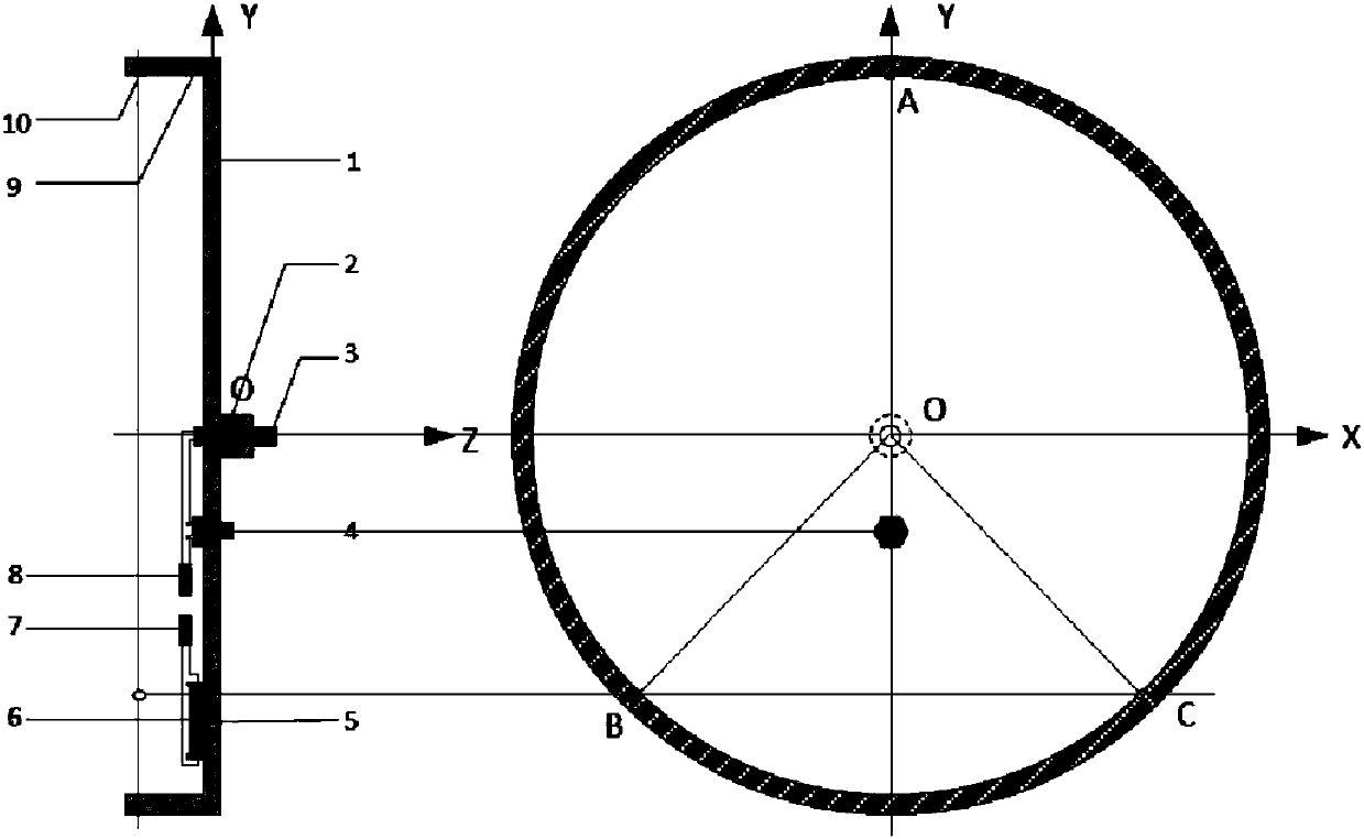
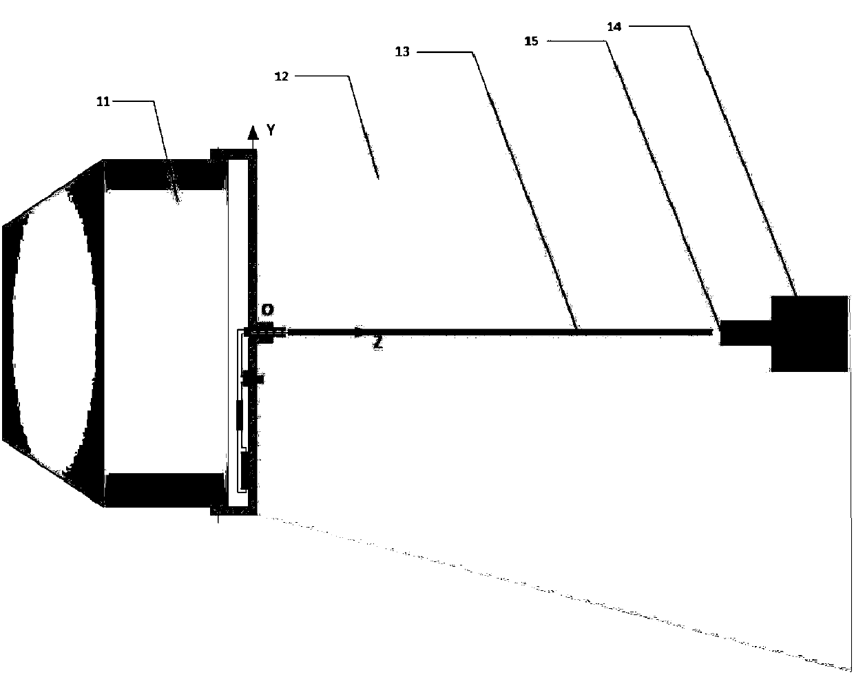
[0036] The present invention discloses a thruster ion beam central line laser positioning scheme, which integrates basic modules such as laser head, collimator, leveler, adjustment screw, switch and battery on the fixture, and the high brightness produced by the laser head , A directional laser beam with good monochromaticity, using the characteristic that the directional laser beam coincides with the centerline of the ion optical system of the thruster and the centerline of the ion beam flow, to accurately position the measuring probe placed in the ion beam flow environment , effectively overcome the problem of inaccurate positioning of the Faraday probe and E×B probe in measuring the thruster beam characteristics. Moreover, this method is simple, easy to implement, and low in cost, and is suitable for Faraday probes and E×B probes in the measurement of v...


PUM


Abstract

The invention discloses a thruster ion beam current center line laser positioning device and method. According to the method, basic modules of a laser head, a collimator, a gradienter, a horizontal adjusting bolt, a switch, a battery and the like are integrated on a clamp, and directional laser beams with high brightness and high monochromaticity are generated by the laser head. According to the feature that the directional laser beams coincide with thruster ion optical system center lines and ion beam current center lines, a measuring probe arranged in an ion beam current environment is precisely positioned, and the problem that a Faraday probe and an ExB probe are inaccurate in positioning in the aspect of measuring features of thruster beam currents is effectively solved. Moreover, themethod is simple and feasible, low in cost, and applicable to precise positioning of the Faraday probe and the ExB probe in the measurement process of various thruster thrust vector deflection angles,beam current divergence angles and bio-charge ion ratios in plume.

Description

technical field [0001] The invention relates to a thruster ion beam centerline laser positioning device, in particular to a Faraday-based laser positioning device used in the measurement of various thruster thrust vector deflection angles, beam divergence angle measurement, and double-charged ion ratio measurement in the plume. Precise positioning field for probes and E×B probes or micro thrust measurement sensors. Background technique [0002] The thruster is a propulsion system that uses electric energy to heat, dissociate, and accelerate the working medium to form a high-speed jet to generate thrust. The thruster technology has been widely used in satellite position maintenance and attitude control due to its high specific impulse, portability, and cleanliness. , Orbit transfer has become one of the most effective means to increase the payload of satellite platforms and extend the working life of satellites. [0003] The thruster needs to measure the beam characteristics...

Claims


Application Information

Patent Timeline
Patent Type & Authority Applications(China)
IPC IPC(8): G01T1/29G01T7/00G01C15/00
CPCG01T1/29G01C15/004G01C15/008G01T1/2907G01T7/005
Inventor 田恺史楷杨俊泰马彦坤王蒙郑茂繁高俊陈焘田东鹏马昕徐金灵柏树
Owner LANZHOU INST OF PHYSICS CHINESE ACADEMY OF SPACE TECH
Why Eureka
Try Eureka