
Gluing device for lamination machine

A technology of glue sticking device and lamination machine, which is applied in battery assembly machine, sustainable manufacturing/processing, climate sustainability, etc. It can solve the problems of not sticking the tape very firmly, reverse side of battery separator, troubles of producers, etc. , to achieve the effect of ensuring firmness, preventing the reverse side of the diaphragm, and improving market competitiveness

Pending Publication Date: 2018-02-27
东莞市沈海自动化科技有限公司
View PDF0 Cites 4 Cited by
  • Summary
  • Abstract
  • Description
  • Claims
  • Application Information

AI Technical Summary

Problems solved by technology

[0003] The gluing mechanism in the prior art uses a gluing brush to smear the glue, which has the following disadvantages: it is easy to cause the battery separator to be glued to be reversed or wrinkled seriously, and it is very unstable, and the gluing will also cause the tape to be stuck incorrectly. Strong, causing great distress to producers

Method used


Image

  • Gluing device for lamination machine
  • Gluing device for lamination machine
  • Gluing device for lamination machine

Examples


Embodiment Construction

[0019] The present invention will be further described below in conjunction with specific embodiments and accompanying drawings.

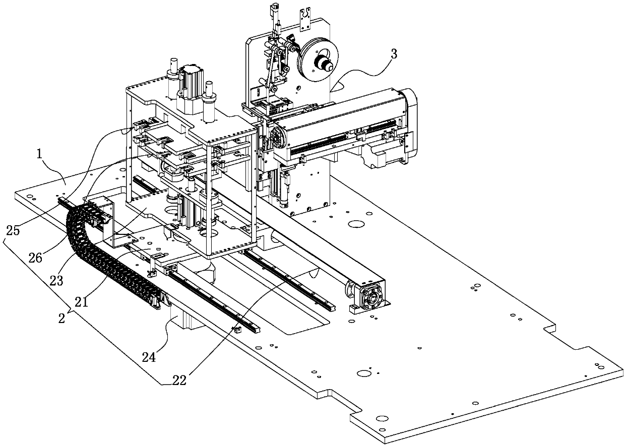
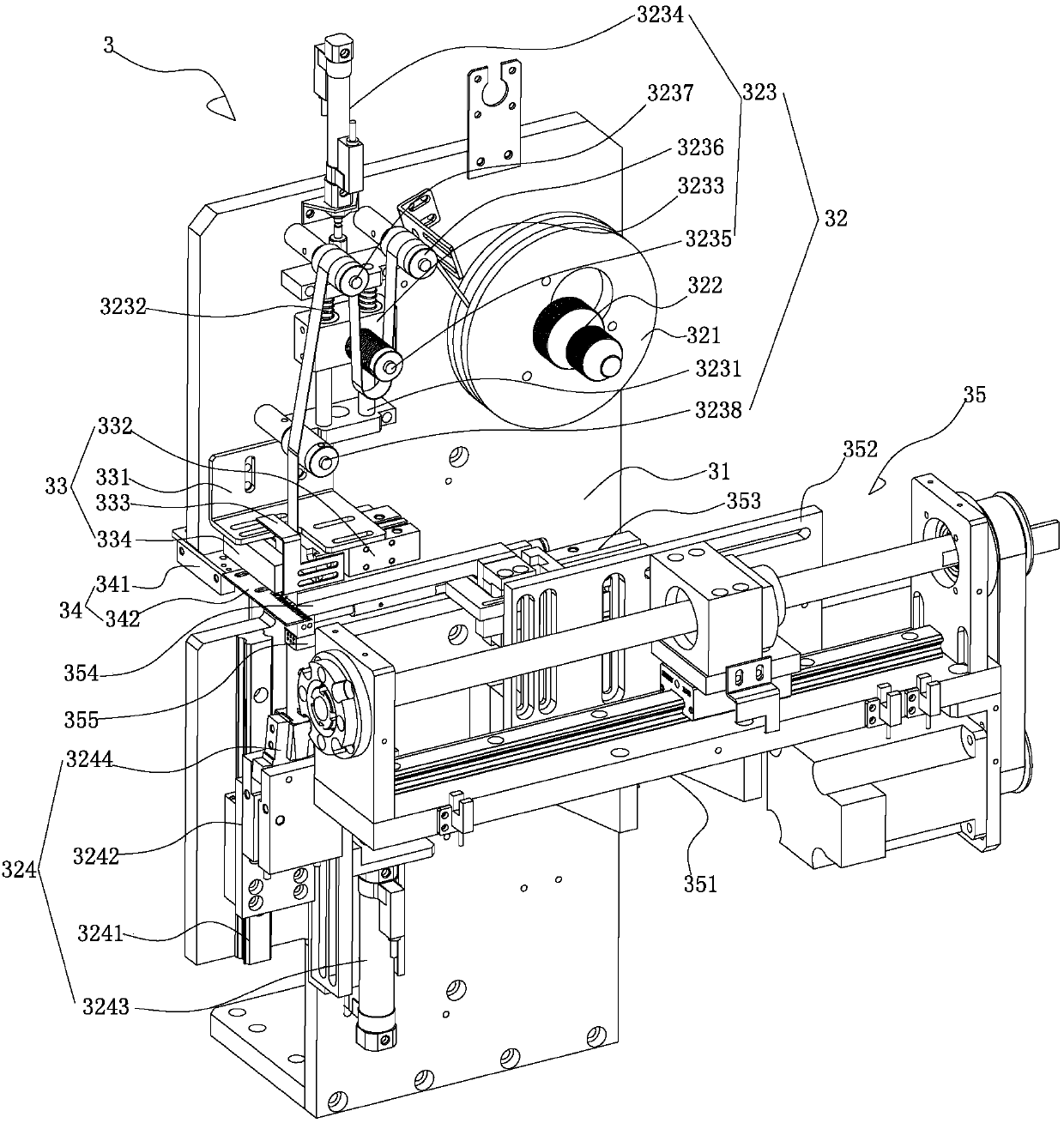
[0020] See Figure 1-3 Shown is a gluing device for a laminate machine, which includes: a substrate 1 , a gluing platform module 2 installed on the substrate 1 , and a gluing mechanism 3 adapted to the gluing platform module 2 .

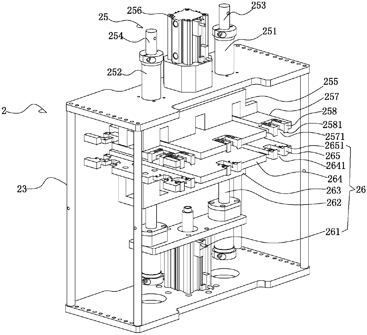
[0021] The gluing platform module 2 includes a moving base 21 movably installed on the base plate 1, a first linear drive module 22 installed on the base plate 1 and used to drive the moving base 21 to move horizontally, and a first linear drive module 22 installed on the moving base 21. The rotating frame 23, the motor assembly 24 installed on the lower end of the moving base 21 and used to drive the rotation of the rotating frame 23, the first positioning splint module 25 and the second positioning splint module 25 installed in the rotating frame 23 and can be mutually clamped or opened Plywood module 26, between the f...


PUM


Abstract

The invention discloses a gluing device for a lamination machine. The gluing device comprises a substrate, a gluing platform module and a gluing mechanism, wherein the gluing platform module comprisesa moving seat, a first linear drive module, a rotating rack, a motor assembly, a first positioning clamping plate module and a second positioning clamping plate module; the moving seat is movably arranged on the substrate; the first linear drive module is arranged on the substrate and is used for driving the moving seat to horizontally move; the rotating rack is mounted on the moving seat; the motor assembly is arranged at the lower end of the moving seat and is used for driving the rotating rack to rotate; the first positioning clamping plate module and the second positioning clamping platemodule are mounted in the rotating rack, and a clamping space used for clamping sheets is formed between the first and second positioning clamping plate modules; the gluing mechanism comprises a vertical plate, a surface sizing module, a degumming module, a cutting module and a gluing module; the vertical plate is arranged on the substrate; the surface sizing module is arranged on the vertical plate and is used for transferring adhesive tapes; the degumming module is arranged on the vertical plate and positioned at the lower end of the surface sizing module; the cutting module is arranged on the vertical plate and is used for cutting off the adhesive tapes; the gluing module is arranged on the vertical plate and is used for adsorbing and positioning the cut adhesive tapes and transferringthe adhesive tapes to be attached to the outer sides of laminated sheets clamped by the first and second positioning clamping plate modules.

Description

Technical field: [0001] The invention relates to the technical field of lamination machine products, in particular to a gluing device for lamination machines. Background technique: [0002] The general functional modules of laminators currently on the market include material boxes, secondary positioning and shaping devices, positioning mechanisms, eager cutting devices, clamping mechanisms, lamination mechanisms, diaphragm unwinding tension edge correction mechanisms, material transfer mechanisms, and winding mechanisms. The difference is that the layout of each mechanism on the equipment is different, but most of them belong to the horizontal layout, that is, all the mechanisms are installed on the horizontal bottom plate. [0003] The gluing mechanism in the prior art uses a gluing brush to smear the glue, which has the following disadvantages: it is easy to cause the battery separator to be glued to be reversed or wrinkled seriously, and it is very unstable, and the gluin...

Claims


Application Information

Patent Timeline
IPC IPC(8): H01M10/04
CPCH01M10/0404Y02P70/50
Inventor 崔海冰
Owner 东莞市沈海自动化科技有限公司
Learn More