
Solar panel junction box shaping welding head assembly

A board junction box and solar energy technology, which is applied in the field of solar panel junction box stereotyped welding head components, can solve the problems of insufficient welding, unsightly welding, poor applicability, etc., and achieve the effect of firm solder joints, compact structure, and stable operation

Pending Publication Date: 2021-01-15
苏州晟成智能装备有限公司
View PDF0 Cites 1 Cited by
  • Summary
  • Abstract
  • Description
  • Claims
  • Application Information

AI Technical Summary

Problems solved by technology

[0002] As the appeal for environmental protection becomes stronger and stronger, the country is gradually changing the traditional power generation mode and increasing the proportion of new energy and clean energy. Among them, solar power generation has developed rapidly, so the demand for solar modules is also growing rapidly. The junction box on the solar panel needs to be welded. At present, the welding mechanism used in the market has the effects of low efficiency and unsightly welding. In the actual welding process, it is easy to have insufficient welding and false welding. There are often differences between adjacent welding points. It is difficult for fixed welding devices to meet the welding requirements of products of different sizes. The applicability is poor and the cost is high. Based on the above defects and deficiencies, it is necessary to improve the existing technology and design a solar panel wiring Box shaped welding head assembly

Method used


Image

  • Solar panel junction box shaping welding head assembly
  • Solar panel junction box shaping welding head assembly
  • Solar panel junction box shaping welding head assembly

Examples


Embodiment Construction

[0018]The preferred embodiments of the present invention will be described in detail below with reference to the accompanying drawings, so that the advantages and features of the present invention can be more easily understood by those skilled in the art, so as to make a clearer and clearer definition of the protection scope of the present invention.

[0019]SeeFigure 1 to Figure 4, The embodiment of the present invention includes:

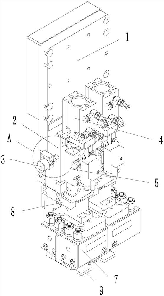
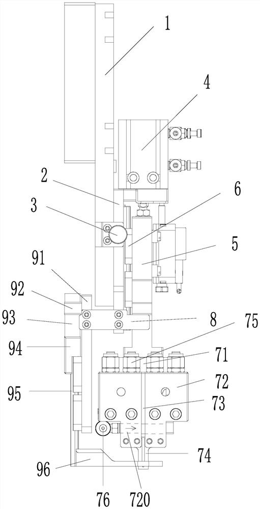
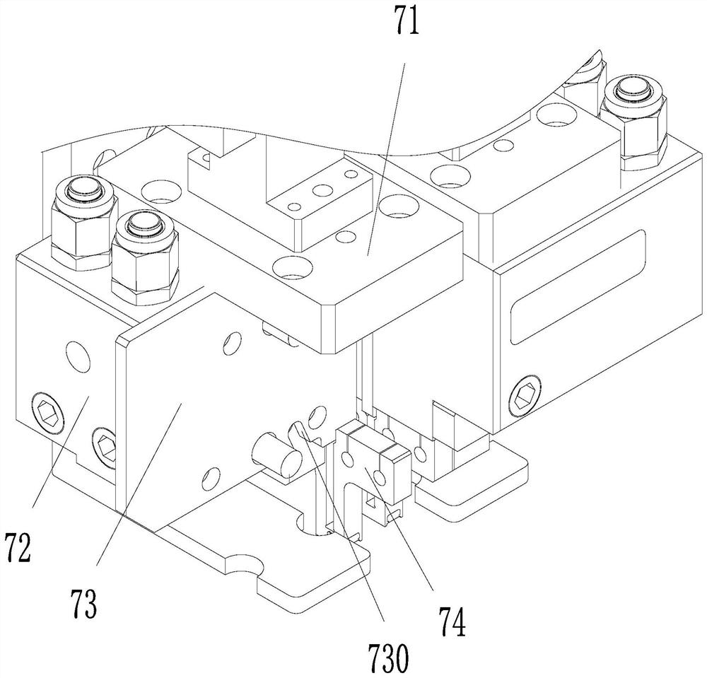
[0020]A solar panel junction box stereotyped welding head assembly. The solar panel junction box stereotyped welding head assembly includes a main mounting plate 1, a horizontal adjustment plate 2, an adjustment assembly 3, a guide rod cylinder 4, a lifting plate 5, and a linear slide 6. The welding head assembly 7, the limit block 8 and the pressure plate assembly 9. The main mounting plate 1 is equipped with two horizontal adjustment plates 2 with adjustable horizontal positions. The two sides of the main mounting plate 1 are installed with functions acting...


PUM


Abstract

The invention discloses a solar panel junction box shaping welding head assembly. The solar panel junction box shaping welding head assembly comprises a main mounting plate, two horizontal adjusting plates, adjusting assemblies, guided cylinders, a lifting plate, a linear sliding rail, a welding head assembly, a limiting block and a pressing plate assembly, wherein the two horizontal adjusting plates are installed on the main mounting plate, the adjusting assemblies are installed at the two side ends of the main mounting plate, the guided cylinders are installed on the horizontal adjusting plates, piston rods of the guided cylinders are fixedly connected with the lifting plate through connecting blocks, the lifting plate is slidably connected with the horizontal adjusting plates through the vertically-arranged linear sliding rail, the welding head assembly is installed at the lower end of the lifting plate, the pressing plate assembly is arranged below the welding head assembly, and the pressing plate assembly is movably connected with the main mounting plate. By means of the mode, the solar panel junction box shaping welding head assembly is flexible and convenient to operate, fast in temperature rise, high in temperature resistance, capable of guaranteeing that welding spots are firm, wide in the application range, and capable of rapidly cooling the welding head and a weldedproduct, avoiding the damage to the product, and preventing the welding head from being adhered.

Description

Technical field[0001]The invention relates to the technical field of solar component manufacturing, in particular to a shaped welding head component of a solar panel junction box.Background technique[0002]As the call for environmental protection becomes stronger and stronger, the country is gradually changing the traditional power generation mode, increasing the proportion of new and clean energy power generation. Among them, solar power generation has developed rapidly, so the demand for solar modules is also growing rapidly. The junction box on the solar panel needs to be welded. At present, the welding mechanism used in the market has low efficiency and unsightly welding. In the actual welding process, it is prone to improper welding and false welding. In addition, for the same type of products, There are often differences between adjacent welding points. The fixed welding device is difficult to meet the welding requirements of products of different sizes. It has poor applicabili...

Claims


Application Information

Patent Timeline
Patent Type & Authority Applications(China)
IPC IPC(8): B23K37/00B23K37/02
CPCB23K37/0211B23K37/003
Inventor 冯鑫吕青涛
Owner 苏州晟成智能装备有限公司
Learn More