High-holding-power ship anchor and ship

An anchor and grip technology, applied in anchor points, ship parts, ship construction, etc., can solve the problems of poor balance and stability, unstable center of gravity, prone to overturning and tilting, etc., to ensure strength and balance, Improve the anchoring speed and strengthen the effect of the connecting structure

Inactive Publication Date: 2018-03-02
ZHEJIANG OCEAN UNIV
View PDF7 Cites 4 Cited by
  • Summary
  • Abstract
  • Description
  • Claims
  • Application Information

AI Technical Summary

Problems solved by technology

[0002] The anchor is mostly used on ships or other floating bodies. The working principle of the anchor is to hook the river bottom or the reef on the river bottom through the anchor claw to pull the anchor handle, and the anchor handle pulls the anchor chain, and the anchor chain is connected to the hull. If the boat is fixed in this way, when there are not many reefs, or the soil at the bottom of the river is relatively hard and cannot be naturally bitten into the bottom of the river by the anchor, the anchor will not be able to fix the boat well, and the boat will not be able to park on the river. somewhere above
[0003] The high holding power anchor is a product that connects the anchor shank and the anchor fluke to form a suspension structure. Because the high holding power anchor has the characteristics of large holding power and reliable anchor position, it is widely used in large ships or ocean engineering. If the large The anchor fluke of the gripping anchor does not have a reinforced support structure. After entering the water, the anchor fluke will be impacted by the water flow, and the center of gravity will be unstable, causing the anchor fluke to flip and tilt, and the rigidity is poor, and it is easy to deform. In addition, the anchor fluke is easily affected by the water flow after entering the water. Shock, prone to tipping and tipping, poor balance and stability

Method used


Image

  • High-holding-power ship anchor and ship
  • High-holding-power ship anchor and ship
  • High-holding-power ship anchor and ship

Examples


Embodiment 1

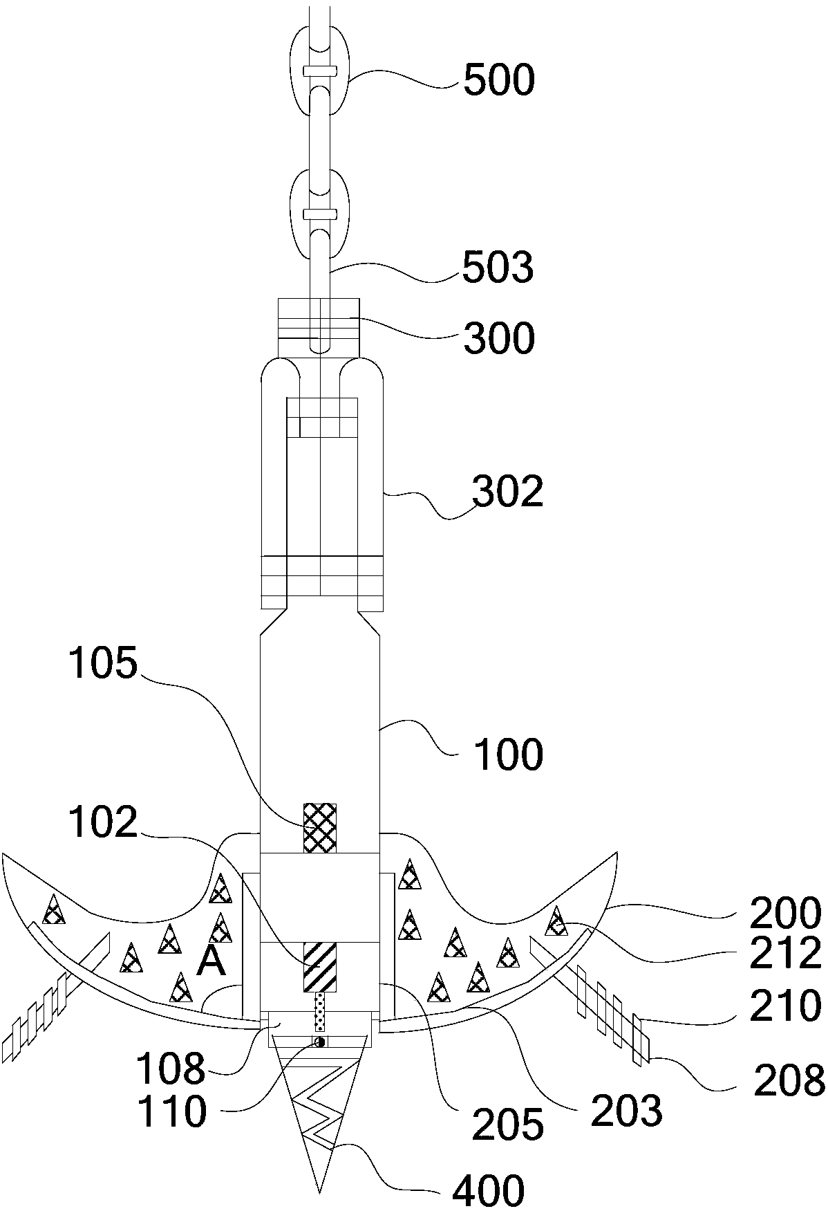
[0034] Such as figure 1 and Figure 4 As shown, the present invention provides a ship anchor with a large holding force, which includes: an anchor handle 100, a fluke 200 symmetrically arranged on the side edge of the bottom of the anchor handle 100, and a The rotating ring 300 , an anchor cone 400 rotatably provided at the bottom end of the anchor handle 100 , and the anchor chain 500 connected with the rotating ring 300 .

[0035] The end of the anchor chain 500 connected to the rotating ring 300 is an anchor end chain 503 ; the anchor end chain 503 is connected to the rotating ring 300 through bolts 505 . The swivel ring 300 is connected to the anchor handle 100 through an anchor shackle 302 .

[0036] see image 3 As shown, specifically, the end of the rotating ring 300 is cylindrical, and an external thread is provided on the end, and a nut 305 is installed on the anchor shackle 302, and the rotating ring 300 is screwed into the nut 305, and the tail of the rotating ri...

Embodiment 2

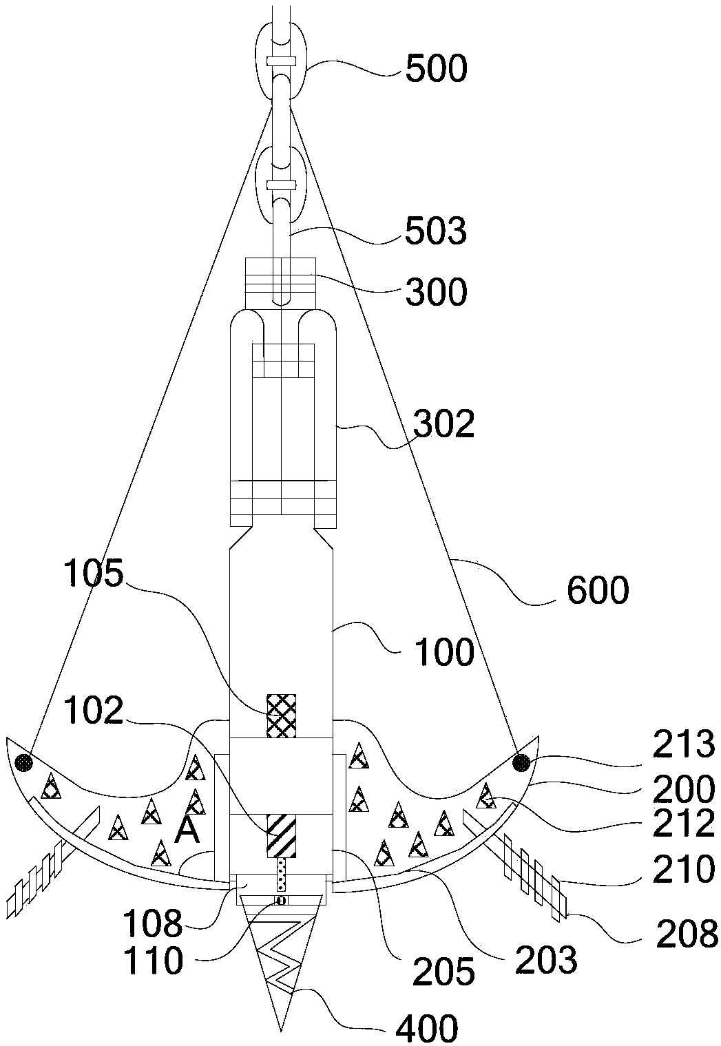
[0051] see figure 2 As shown, on the basis of Embodiment 1, the large-grasp anchor of this embodiment has roughly the same structure as that of Embodiment 1, the difference being that the fluke 200 of the large-grasp anchor of this embodiment A chain 600 connected to the anchor chain 500 is provided at the end angle of the chain, and the chain 600 can optionally adopt a steel rope. The chain 600 provided in this embodiment plays the role of assisting the anchoring, so that when the anchor is lifted, the whole ship's anchor can be exerted and pulled, so that the anchor can be lifted more quickly. Because the anchoring force of the ship anchor of the present invention on the seabed soil layer is strong, in the process of lifting the anchor, the anchoring force relying on the single point of the anchor chain 500 on the top of the anchor handle 100 may have relatively large resistance, so through the set chain 600, Realize multi-point force application and reduce anchor resistan...

Embodiment 3

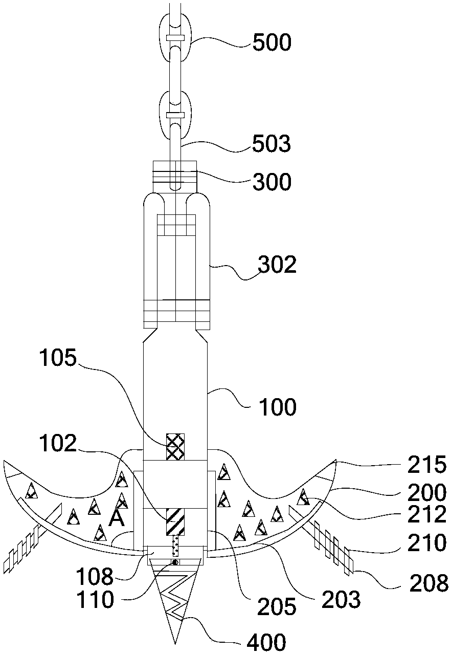
[0054] see image 3 As shown, on the basis of embodiment 1 or embodiment 2, the large grasping force anchor of the present embodiment has roughly the same structure as the large grasping force anchor of embodiment 1 or embodiment 2, the difference is that the large grasping force anchor of the present embodiment A detachable claw head 215 is provided at the corner of the fluke 200 of the gripping anchor which is not in contact with the anchor handle 100 . The claw head 215 is connected by, for example but not limited to, a screw-nut connection. The claw head 215 is designed as a detachable assembly method, which is convenient for timely replacement when the claw head 215 is damaged and deformed, because the anchor claw itself often contacts stones or slurry stones, and is easily deformed and damaged.


PUM


Abstract

The invention relates to the technical field of ships and marine engineering manufacturing technology and especially relates to a high-holding-power ship anchor and a ship. The high-holding-power shipanchor comprises an anchor handle, anchor flukes are symmetrically installed at a bottom side edge of the anchor handle, a rotating ring installed on a top of the anchor handle and an anchor cone which is installed at a bottom of the anchor handle; and an anchor chain which is connected with the rotating ring; the end part connecting the anchor chain and the rotating ring is an anchor end chain;the rotating ring is connected with the anchor handle through an anchor shackle; a rotating motor which is connected with the anchor cone is installed above the anchor cone in the anchor handle innerchamber and the anchor cone is driven by the rotating motor to drill downward; the anchor handle inner chamber is also provided with a vibrator; reinforcement plates are vertically installed at two sides of the bottom of the anchor flukes; two sides of the anchor handle are provided with a fixing board vertically connected with the anchor flukes; one end of the fixing board is connected with one end of the reinforcement board; a balancing rod is installed at one side, away from the anchor handle, on the anchor fluke.

Description

technical field [0001] The invention relates to the technical field of ship and marine engineering manufacturing, in particular to a ship anchor with a large holding force and a ship. Background technique [0002] The anchor is mostly used on ships or other floating bodies. The working principle of the anchor is to hook the river bottom or the reef on the river bottom through the anchor claw to pull the anchor handle, and the anchor handle pulls the anchor chain, and the anchor chain is connected to the hull. If the boat is fixed in this way, when there are not many reefs, or the soil at the bottom of the river is relatively hard and cannot be naturally bitten into the bottom of the river by the anchor, the anchor will not be able to fix the boat well, and the boat will not be able to anchor on the river. a position above. [0003] The high holding power anchor is a product that connects the anchor handle and the anchor fluke to form a suspension structure. Because the high...

Claims


Application Information

Patent Timeline
Patent Type & Authority Applications(China)
IPC IPC(8): B63B21/22B63B21/26
CPCB63B21/22B63B21/26
Inventor 苏玉香范瑞钦
Owner ZHEJIANG OCEAN UNIV
Why Eureka
Try Eureka