Semi-submersible type hydraulic testing device for vertical and axial suction centrifugal pump

A testing device and centrifugal pump technology, applied in the mechanical field, can solve problems such as large axial force and inability to directly measure NPSH, and achieve the effects of convenient installation and adjustment, improving versatility and application ability, and expanding the range of models

Pending Publication Date: 2018-03-02
SHANGHAI PUMP MFR
View PDF0 Cites 12 Cited by
  • Summary
  • Abstract
  • Description
  • Claims
  • Application Information

AI Technical Summary

Problems solved by technology

Under the same rated flow rate, the multistage pump has a discharge pressure equivalent to that of multiple single-stage water pumps, so the axial force that needs to be balanced on the rotor of the multistage vertical pump is relatively large, and the axial force includes self-gravity; most centrifugal The pump has a suction performance item in the hydraulic test. The NPSH of the pump is directly related to the installation height of the pump suction. However, due to the limitation of the installation center of gravity and the structure of the vertical pump, it is often impossible to directly measure the NPSH. For the suction centrifugal pump group, the size of the rotor installation structure is usually longer, especially the multi-stage vertical pump is more prominent. The device bench used by the pump manufacturer to test the vertical centrifugal water pump has always the installation space in the factory building. There are limitations, and pump test activities mean repeated hoisting operations, which involve a series of factors related to hoisting space, such as various vertical pump structures and types, sizes and hoisting heights, port diameters and positions, and equipment weight and support.

Method used


Image

  • Semi-submersible type hydraulic testing device for vertical and axial suction centrifugal pump
  • Semi-submersible type hydraulic testing device for vertical and axial suction centrifugal pump

Examples


Embodiment Construction

[0021] The specific implementation manners of the present invention will be further described below in conjunction with the drawings and examples. The following examples are only used to illustrate the technical solution of the present invention more clearly, but not to limit the protection scope of the present invention.

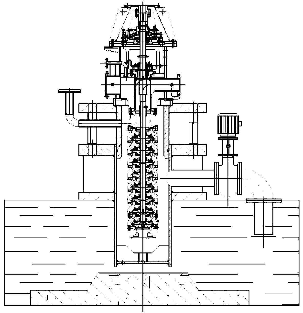
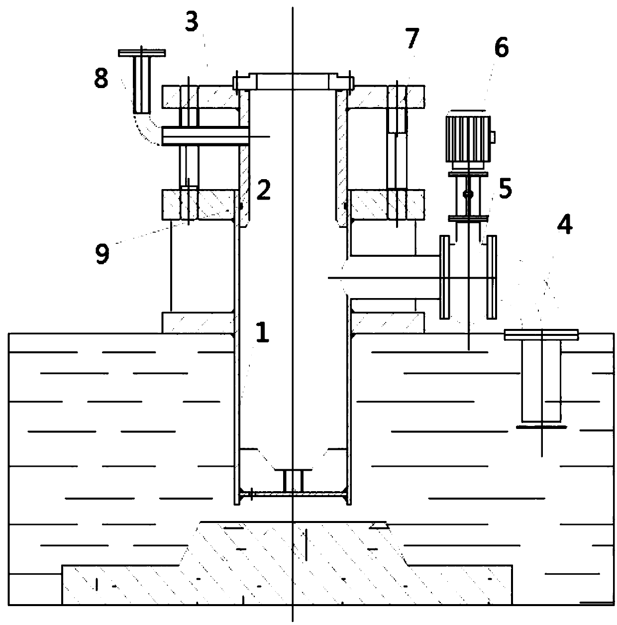
[0022] A vertical axial suction centrifugal pump semi-submersible hydraulic test device, such as figure 2 As shown, it includes test cylinder 1, lifting platform 2, water suction pipeline 4, executive motor 6, adjustment screw 7 and degassing pipe 8, water suction pipeline 4 is set on the right side of test cylinder 1, water suction pipeline 4 and The test cylinders 1 are connected to each other, and the test cylinder 1 is provided with a sealing filler 9 to make the test cylinder 1 in a better sealed state. The water suction pipeline 4 is also provided with a regulating valve 5 for NPSH test During the process, the vacuum degree in the test cylinder is a...


PUM


Abstract

The invention relates to the field of mechanical technology, in particular to a semi-submersible hydraulic testing device for a vertical axial suction centrifugal pump, which includes a test cylinder, a lifting platform, a water suction pipeline, an actuator motor, an adjustment screw, a degassing pipe, and a water suction pipeline It is located on one side of the test cylinder, and the water suction pipeline is connected with the test cylinder. There is also a regulating valve on the water suction pipeline, and an adapter plate is installed on the lifting platform, so that the pump body to be tested can be installed on the lifting platform through the adapter plate. On the top, there is an adjustment screw between the lifting platform and the adapter plate. By adjusting the screw, the vertical position adjustment of the lifting platform is realized. The executive motor is installed on the water suction pipeline and connected with the regulating valve. A degassing tube is also provided on the other side. The invention provides a semi-submersible hydraulic testing device capable of adapting and matching various types of vertical pumps, improving the universality and application ability of the testing device, and bringing convenience to the installation and adjustment of the vertical centrifugal pump testing process.

Description

technical field [0001] The invention relates to the field of mechanical technology, in particular to a semi-submersible hydraulic testing device for a vertical axial suction centrifugal pump. Background technique [0002] Vertical axial suction centrifugal water pumps include single-stage or multi-stage pumps. Generally, the pump body has a compact structure and a small footprint. The driving motor of the water pump is usually installed directly on the pump body, or indirectly installed on the pump vertical. above the axis. Under the same rated flow rate, the multistage pump has a discharge pressure equivalent to that of multiple single-stage water pumps, so the axial force that needs to be balanced on the rotor of the multistage vertical pump is relatively large, and the axial force includes self-gravity; most centrifugal The pump has a suction performance item in the hydraulic test. The NPSH of the pump is directly related to the installation height of the pump suction. H...

Claims


Application Information

Patent Timeline
Patent Type & Authority Applications(China)
IPC IPC(8): F04D15/00
CPCF04D15/0088
Inventor 朱力强陈永波
Owner SHANGHAI PUMP MFR
Why Eureka
Try Eureka