A pull-type nitrogen balancer

A technology of balancer and nitrogen, which is applied in the direction of metal processing equipment, maintenance and safety accessories, metal processing machinery parts, etc., can solve the problems of easy rise of oil temperature in the hydraulic circuit, slow response speed, heavy machine tool weight, etc., to ensure reliability performance, fast response, and easy retrofitting

Active Publication Date: 2019-05-31
张艳东
View PDF5 Cites 0 Cited by
  • Summary
  • Abstract
  • Description
  • Claims
  • Application Information

AI Technical Summary

Problems solved by technology

[0004] Disadvantages of the oil pressure balancer: The oil pressure balancer needs a hydraulic unit and piping, and the oil temperature of the hydraulic circuit is extremely easy to rise, so it needs to be cooled. Another type of oil pressure balancer is to make the whole set of balancer into a pressure maintaining system , with a standard accumulator tank for energy storage, when the piston is compressed, the oil is pressed into the accumulator, and when the piston is released, the oil is spit out from the accumulator, because the accumulator is a bladder or diaphragm type , the service life of the accumulator is low, and the oil pressure response speed is much slower than that of the pneumatic type, so the process beat will be slowed down a lot
[0005] Disadvantages of the counterweight balancer: slow response speed, which makes the work cycle much slower, which leads to a lot of difference in the response speed of the entire machine tool
[0006] Disadvantages of compressed air balancer: the response speed of compressed air balancer is much improved, but the compressed air balancer needs to balance the force is fixed, the standard pressure of compressed air is 0.4-0.8MPa, so the compressed air balancer needs to make a cylinder The diameter is very large, occupying a large space in the design of the machine tool, resulting in a heavy weight of the machine tool itself
[0007] Disadvantages of top-top nitrogen balancer: such as figure 1 As shown, although the top-top nitrogen balancer solves the problem of slow response, because its installation position must be at the bottom of the spindle head, it occupies a large part of the design space of the machine tool; in addition, for compact machine tools, due to this part The space of the machine tool is limited, and to meet the balance requirements of the spindle head, the balancer will be made very large, even too large to be installed in the limited space of the machine tool

Method used


Image

  • A pull-type nitrogen balancer
  • A pull-type nitrogen balancer
  • A pull-type nitrogen balancer

Examples


Embodiment Construction

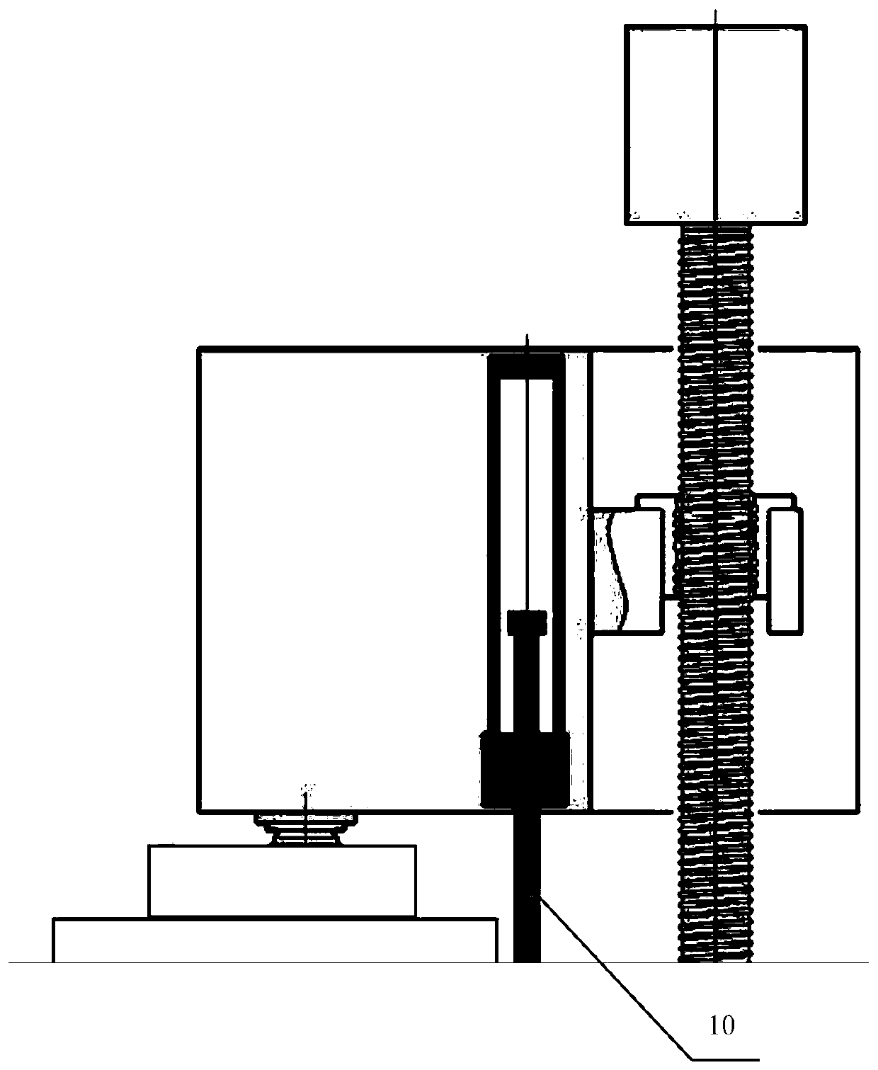
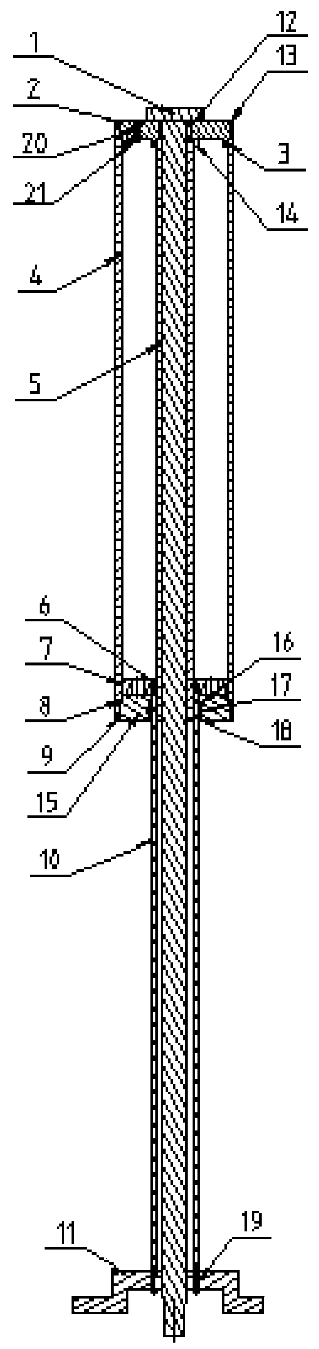
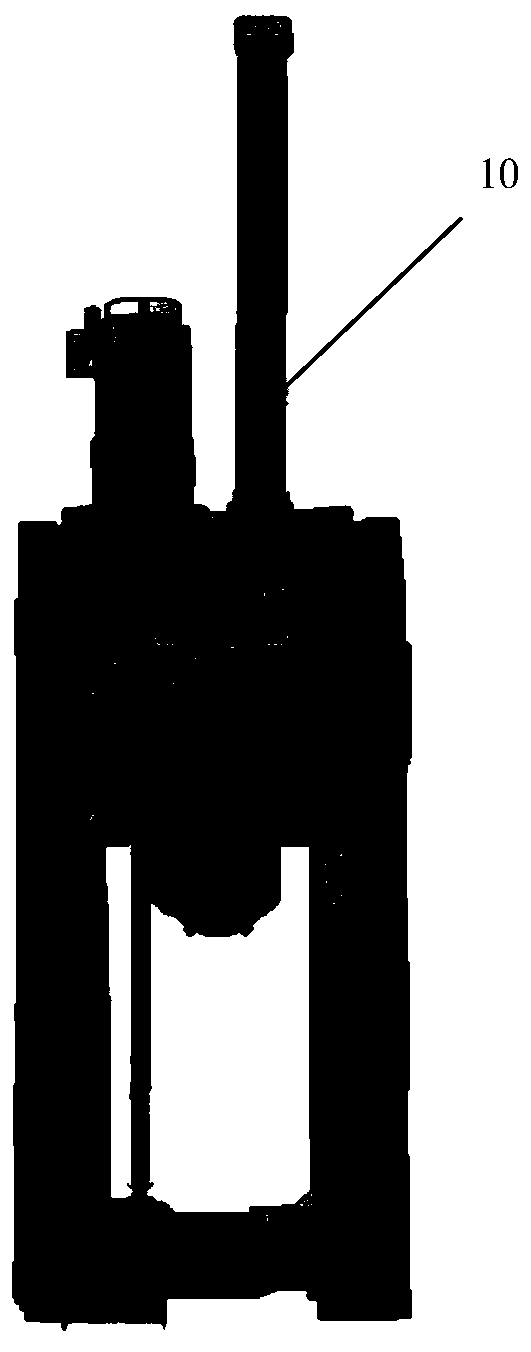
[0029] The present invention will be further described below in conjunction with the accompanying drawings. like figure 2 As shown, a pull-type nitrogen balancer includes a connecting rod 1, a cylinder assembly, a guide tube 5, a piston 10 and a support seat 11;

[0030] The guide pipe 5 is fixed in the cylinder assembly, and the outer surface of the guide pipe 5 and the inner surface of the cylinder assembly form a closed cavity for storing gas; The outer surface of 5 is movably connected, and at the same time is movably connected with the inner surface of the cylinder assembly; the lower end of the piston 10 is fixed on the support seat 11, and the support seat 11 is fixed on the frame above the spindle head; The connecting rod 1 passes through the upper end cover 2, the guide tube 5, the piston 10 and the support seat 11 and is connected to the spindle head.

[0031] Further, the cylinder body assembly includes a cylinder body 4, an upper end cover 2 and a lower end cove...


PUM


Abstract

The invention discloses a lifting type nitrogen balancer. The lifting type nitrogen balancer comprises a connecting rod, a cylinder block assembly, a guide pipe, a piston and a supporting seat; the guide pipe is fixed in the cylinder block assembly, and a closed cavity for storing gas is formed by the outer side face of the guide pipe and the inner side face of the cylinder block assembly; the upper end of the piston is arranged on the outer side of the guide pipe in a sleeving mode, movably connected with the outer side face of the guide pipe and meanwhile movably connected with the inner side face of the cylinder block assembly; the lower end of the piston is fixed to the supporting seat, and the supporting seat is fixed to a machine frame above a spindle head; and the connecting rod penetrates through an upper end cover, the guide pipe, the piston and the supporting seat and is connected to the spindle head. By the adoption of the nitrogen balance technology, the high response speedof the balancer is guaranteed. By using the hollow piston for replacing a solid piston, the lifting function of the balancer is achieved, the whole balancer can be installed on the machine frame above the spindle head of a machine tool, and the stroke and space of the balancer can meet the large size requirement of a heavy handpiece since the machine frame is not limited by the space and stroke.

Description

technical field [0001] The invention relates to the field of mechanical processing, in particular to a balancer for improving the process beat, work efficiency and processing precision of a machine tool. Background technique [0002] The vertical moving parts of the machine tool are not only affected by the driving force, cutting force, etc., but also by the gravity of its own weight. Since the direction of this force is consistent with the direction of movement of the component, it cannot be supported by a support like a horizontally moving component. If this gravity is not compensated, it will have a negative impact on the smoothness of the movement of the components, and in severe cases, it will cause loss of control. With the development of machine tool manufacturing technology, the movement speed of modern machine tool components is getting faster and faster, and the control precision is getting higher and higher. The traditional hydraulic balance circuit can no longe...

Claims


Application Information

Patent Timeline
Patent Type & Authority Patents(China)
IPC IPC(8): B23Q11/00
CPCB23Q11/001
Inventor 不公告发明人
Owner 张艳东
Why Eureka
Try Eureka