Oil Ventilators, Ventilation Systems and Gas Turbine Engines

A technology for ventilation systems and gas turbines, which is applied in the direction of machines/engines, gas turbine devices, engine components, etc. It can solve the problems of large flow rate of sealing devices, increased lubricating oil consumption, and large lubricating oil consumption, so as to reduce resistance, Effect of reducing oil consumption and improving separation performance

Active Publication Date: 2019-07-02
AECC COMML AIRCRAFT ENGINE CO LTD
View PDF4 Cites 0 Cited by
  • Summary
  • Abstract
  • Description
  • Claims
  • Application Information

AI Technical Summary

Problems solved by technology

In order to ensure that the flow rate of all sealing devices meets the needs, the flow rate of some sealing devices is often too large, thereby increasing the consumption of lubricating oil
In addition, the flow of high-pressure air is related to the speed of the engine. Although the minimum flow required at a certain speed can be determined through calculation, the speed of the engine is different under different states. Under the condition of ensuring the air flow required by the sealing device, There will still be a problem of high air flow at other state points, resulting in excessive oil consumption

Method used


Image

  • Oil Ventilators, Ventilation Systems and Gas Turbine Engines
  • Oil Ventilators, Ventilation Systems and Gas Turbine Engines
  • Oil Ventilators, Ventilation Systems and Gas Turbine Engines

Examples


Embodiment Construction

[0030] The technical solutions in the embodiments will be clearly and completely described below in conjunction with the drawings in the embodiments of the present invention. Obviously, the described embodiments are only a part of the embodiments of the present invention, rather than all the embodiments. Based on the embodiments of the present invention, all other embodiments obtained by those of ordinary skill in the art without creative work fall within the protection scope of the present invention.

[0031] In the description of the present invention, it should be understood that the terms "center", "transverse", "longitudinal", "front", "rear", "left", "right", "upper", "lower", " The orientation or positional relationship indicated by "vertical", "horizontal", "top", "bottom", "inner", "outer" etc. is based on the orientation or positional relationship shown in the drawings, and is only for the convenience of describing the present invention and The description is simplifie...


PUM


Abstract

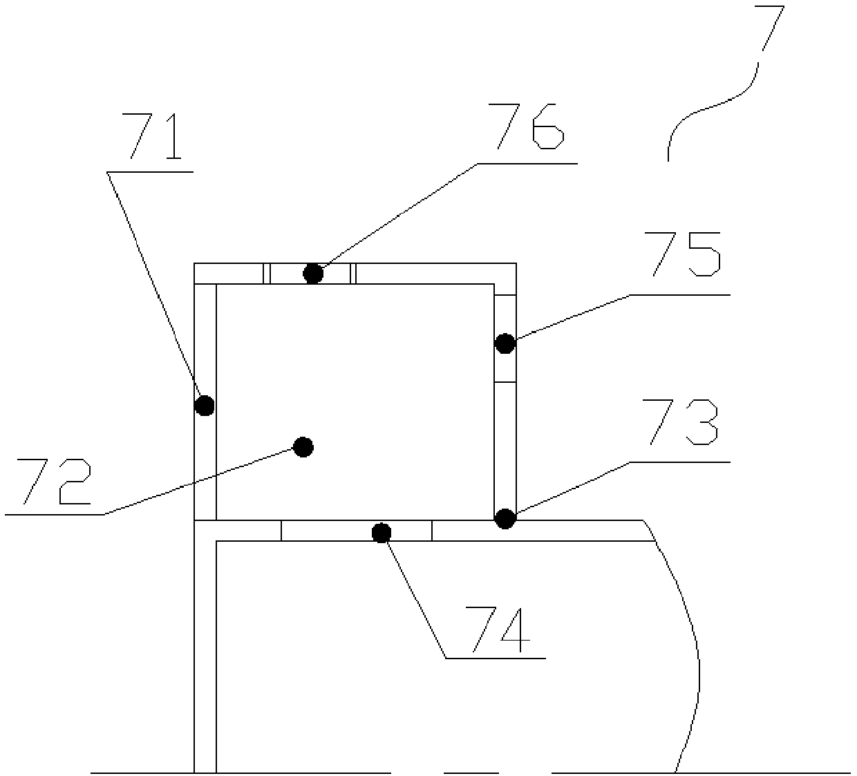
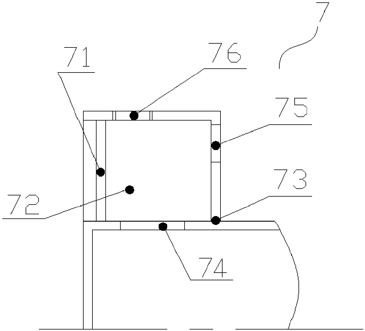
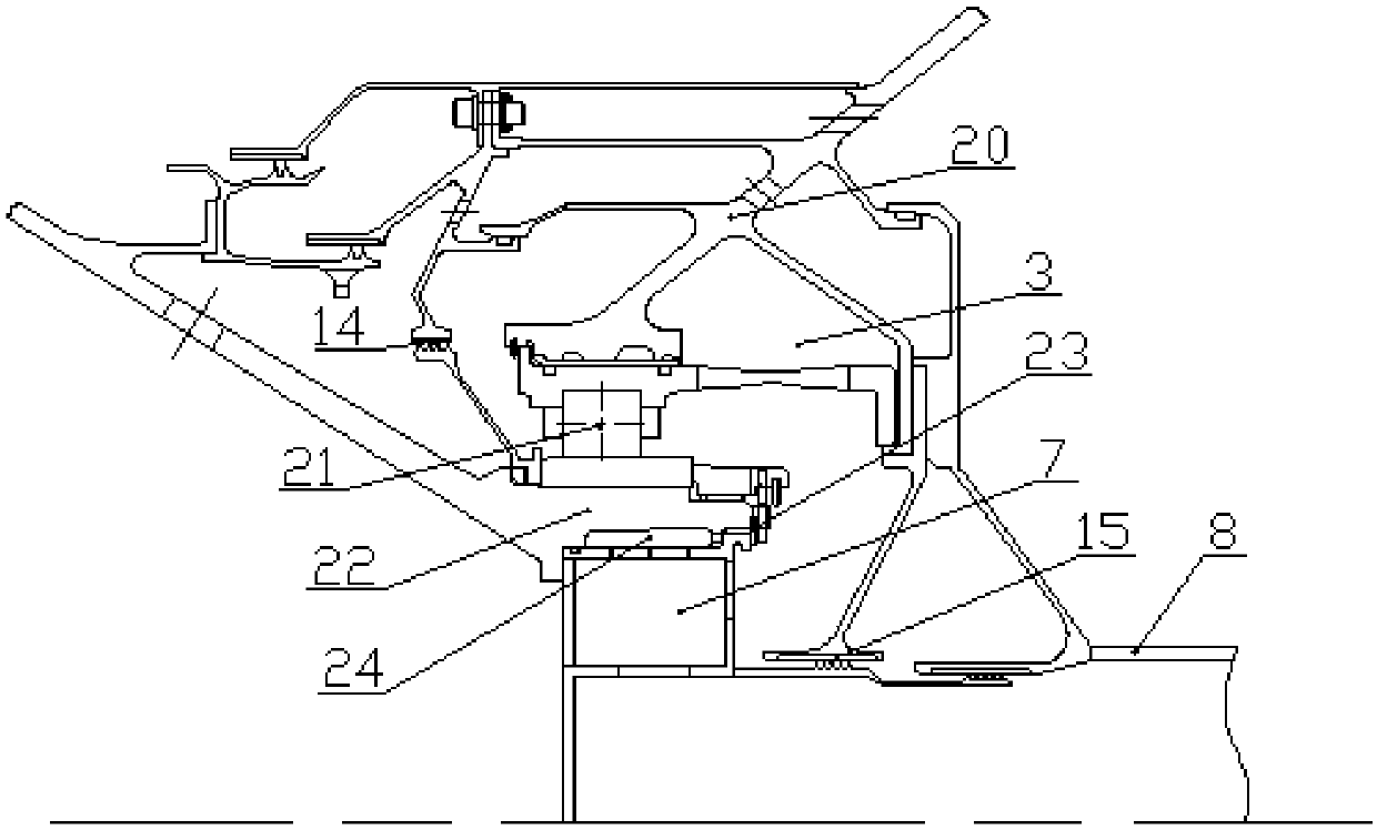
The invention relates to a lubricating oil ventilator, a ventilating system and a gas turbine engine. The lubricating oil ventilator (7) comprises a housing (73) in which a gas-oil separating chamberis arranged, wherein the gas-oil separating chamber is used for gas-oil separation of a gas-oil mixture entering the gas-oil separating chamber; a core body (72) with variable density is arranged in the gas-oil separating chamber and is capable of changing the flowing resistance of the gas-oil separating chamber. According to the lubricating oil ventilator, the flowing resistance of the gas-oil separating chamber can be changed as the demand or as the change of outside conditions; in case of high flow rate of the gas-oil mixture, the core body can be compressed to increase the resistance of the gas-oil separating chamber, thus the time of performing gas-oil separation on the gas-oil mixture in the lubricating oil ventilator can be prolonged, and as a result, the separating performance canbe improved; meanwhile, the volume of lubricating oil drained along with fluid is decreased, and thus the consumption of the lubricating oil is reduced; in case of low flow rate of the gas-oil mixture, the core body can be released to reduce the resistance of the gas-oil separating chamber, and thus the separated gas can flow out normally.

Description

Technical field [0001] The invention relates to the technical field of aeroengines, in particular to a lubricating oil ventilator, a ventilation system and a gas turbine engine. Background technique [0002] A gas turbine engine includes components such as a compressor, a combustion chamber, and a turbine. In order to accurately position and rotatably install the compressor and the rotor of the turbine, bearings are required in the engine. The normal operation of the bearing needs to be reliably lubricated or cooled by lubricating oil. Therefore, the gas turbine engine has an oil cavity for accommodating the bearing. [0003] In order to prevent oil leakage in the lubricating oil cavity, a sealing device is generally arranged between the rotating and stationary parts that constitute the cavity, and high-pressure air is introduced from the compressor part to pressurize the sealing device, and the airflow flowing through the sealing device makes The sealing device has good sealing p...

Claims


Application Information

Patent Timeline
Patent Type & Authority Patents(China)
IPC IPC(8): F02C7/00F02C7/06
CPCF02C7/00F02C7/06
Inventor 王军俞镪鹏曹渝华
Owner AECC COMML AIRCRAFT ENGINE CO LTD
Why Eureka
Try Eureka