Display system
A display system and light modulator technology, applied in optics, instruments, projection devices, etc., can solve the problems of poor feasibility and low light utilization rate, and achieve the goal of improving light recovery efficiency, improving brightness and contrast, and improving light utilization rate. Effect
- Summary
- Abstract
- Description
- Claims
- Application Information
AI Technical Summary
Problems solved by technology
Method used
Image
Examples
Embodiment 1
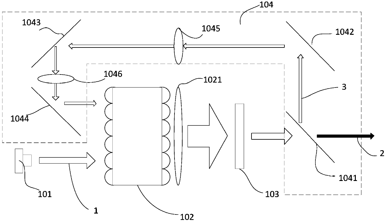
[0047] See Figure 3a , Figure 3a It is a schematic structural diagram of a display system according to Embodiment 1 of the present invention. The display system includes a light source 101 , a dodging device 102 , a light modulator 103 and a light guiding device 104 .
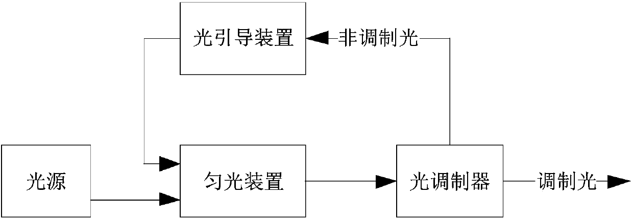
[0048] Wherein, the light source 101 is used to emit the first light 1 , and the homogenization device 102 includes a light incident surface, which is used to receive and homogenize the first light 1 . The light modulator 103 is used for receiving at least part of the light emitted by the dodging device 102 and modulating at least part of the light incident on the light modulator 103 according to the image signal, and emitting modulated light 2 and non-modulated light 3 . The light guiding device 104 is used to guide at least part of the non-modulated light 3 emitted by the light modulator 103 to the light incident surface of the light homogenizing device 102 , so that it enters the light modulator 103 agai...
Embodiment 2
[0072] See Figure 3b , Figure 3b It is a schematic structural diagram of the display system of Embodiment 2 of the present invention. The display system comprises a light source 101, a dodging device 102', a light modulator 103 and a light guiding device 104'. and Figure 3a The difference of the shown first embodiment is that the dodging device 102' in this embodiment is replaced by an integrating rod by a pair of fly-eye lenses.
[0073] In this embodiment, the light modulator 103 is a transmissive liquid crystal light valve, and for a specific description, refer to the description of in the first embodiment above.
[0074] In this embodiment, the light source 101 refers to the description about in the first embodiment.
[0075] In this embodiment, the light guiding device 104' also includes a mirror group composed of multiple mirrors and a lens group composed of multiple relay lenses. The difference is that the light guided by the light guiding device 104' is incid...
Embodiment 3
[0079] See Figure 3c , Figure 3c It is a structural schematic diagram of the display system of Embodiment 3 of the present invention. This embodiment and Figure 3a The difference of the first embodiment mainly lies in the difference in the way of combining the first light and the non-modulated light.
[0080] The display system of this embodiment includes a light source 101, a dodging device 102, a light modulator 103 and a light guiding device 104". The light source 101 is used to emit the first light 1, and the dodging device 102 includes a light incident surface for receiving the first light 1 and make it uniform. The light modulator 103 is used to receive at least part of the light emitted by the light homogenizing device 102 and modulate the light incident on the light modulator 103 according to the image signal, and emit modulated light 2 and non-modulated light 3 . The light guiding device 104 ″ is used to guide at least part of the non-modulated light 3 emitted b...
PUM
 Abstract
Description
Claims
Application Information
 - R&D
- Intellectual Property
- Life Sciences
- Materials
- Tech Scout
- Unparalleled Data Quality
- Higher Quality Content
- 60% Fewer Hallucinations
Browse by: Latest US Patents, China's latest patents, Technical Efficacy Thesaurus, Application Domain, Technology Topic, Popular Technical Reports.
© 2025 PatSnap. All rights reserved.Legal|Privacy policy|Modern Slavery Act Transparency Statement|Sitemap|About US| Contact US: help@patsnap.com


