
Joined wing structure-form wing load measurement method

A technology of structural form and load measurement, applied in the field of flight load flight test, can solve the problems of inapplicability of flight load measurement and large error of load equation, and achieve the effect of improving reliability and accuracy

Active Publication Date: 2018-03-06
CHINESE FLIGHT TEST ESTAB
View PDF9 Cites 7 Cited by
  • Summary
  • Abstract
  • Description
  • Claims
  • Application Information

AI Technical Summary

Problems solved by technology

When measuring the wing load of the connected wing structure, due to the mutual influence of the deformation between the front and rear wings, the measurement section load inside the joint of the front and rear wings has a coupling effect, so that through the conventional wing load calibration test method The error of the obtained load equation is very large, and it is not applicable to the flight load measurement of the wing of this structure

Method used


Image

  • Joined wing structure-form wing load measurement method
  • Joined wing structure-form wing load measurement method
  • Joined wing structure-form wing load measurement method

Examples


Embodiment Construction

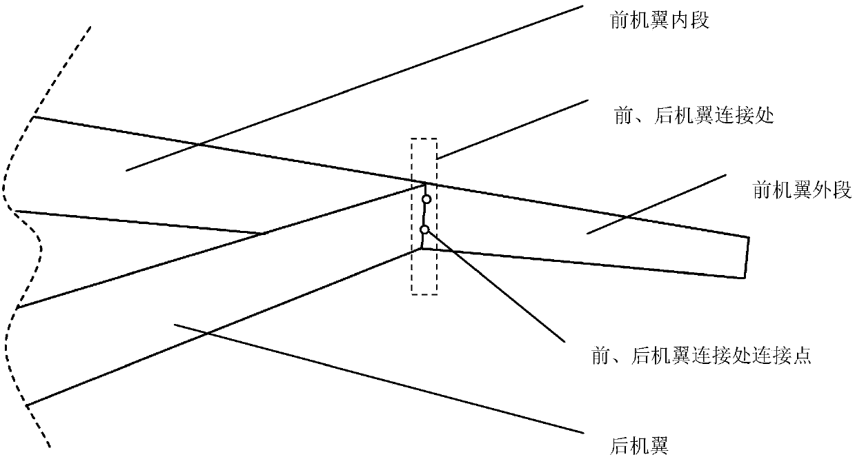
[0044] Such as figure 1 Shown, embodiment of the present invention is as follows:

[0045] (1) Strain gauge bridge modification

[0046] Because the front and rear wing load measurement profile measurement bridges are not sensitive to span loads and chord loads, they are only sensitive to normal loads. In flight, the spanwise and chordwise load components of the wing flight loads produce a measurement bridge output that is of high order and negligible. In the arrangement scheme of the strain gauges, the layout of the electric bridges for the measurement section of the front and rear wings is the same as that of the conventional wings, but each connection point at the connection of the front and rear wings (generally in the form of connecting lugs) needs to be arranged A shear bridge.

[0047] (2) Ground calibration test

[0048] The ground load calibration test is divided into three parts: because the structure of the connecting wing has no effect on the load of the outer ...


PUM


Abstract

The invention relates to a joined wing structure-form wind load measurement method. The method is characterized in that a joined wing structure wing load measurement strain meter arrangement and loadcalibration experiment process is formulated according to joined wing structure-form wind stress characteristics, coupled loads at joined wind structure wing connections are identified, and wind loadmodeling influences caused by connection forms are eliminated, so as to form a joined wing structure form-oriented wind load measurement method. According to the method, influences, on wing measurement load profile strain bridge strain output, of coupled loads caused by the joined wing structure form can be eliminated, so that precision of a joined wing structure-form wing load equation is improved, flight loads of joined wing structure-form wings can be correctly measured, and reliability of flight load measurement results can be improved.

Description

technical field [0001] The present invention relates to flight load flight test, particularly relates to the flight load measurement of the wing of connecting wing structure form during flight. Background technique [0002] Due to its large aspect ratio, small wing load, high stiffness, small deformation and large lift coefficient, the wing with connected wing structure has been widely used in aircrafts pursuing long range and long endurance. When measuring the wing load of the connected wing structure, due to the mutual influence of the deformation between the front and rear wings, the measurement section load inside the joint of the front and rear wings has a coupling effect, so that through the conventional wing load calibration test method The error of the obtained load equation is very large, and it is not applicable to the flight load measurement of the wing with this structure. [0003] Reference [1]: Skopinski T.H, William S.Aiken and Wilber B.Huston: Calibration of...

Claims


Application Information

Patent Timeline
IPC IPC(8): G06F17/50
CPCG06F30/15G06F30/20Y02T90/00
Inventor 钟海田丁栓赵燕刘敬礼王亚龙
Owner CHINESE FLIGHT TEST ESTAB
Learn More