Radio frequency identification (RFID) label and RFID label antenna

A technology for RFID tags and antennas, applied in the field of RFID tags and RFID tag antennas, can solve problems such as small energy transmission coefficient, matching of RFID tag antennas, affecting the reading distance of RFID tags, etc., to achieve lower resonance frequency, good conjugate matching, The effect of improving R&D efficiency

Inactive Publication Date: 2018-03-06
RUIZHANG TECH LTD CO
View PDF6 Cites 7 Cited by
  • Summary
  • Abstract
  • Description
  • Claims
  • Application Information

AI Technical Summary

Problems solved by technology

[0007] However, in the existing PIFA antenna, when the RFID tag antenna is very thin and small in size, it is difficult for the input impedance of the RFID tag antenna to m

Method used


Image

  • Radio frequency identification (RFID) label and RFID label antenna
  • Radio frequency identification (RFID) label and RFID label antenna
  • Radio frequency identification (RFID) label and RFID label antenna

Examples


Embodiment Construction

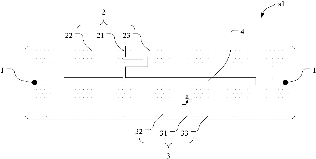
[0037] At present, the size of the existing PIFA antenna is usually designed to be 1 / 4 wavelength at the resonant frequency. Although the PIFA antenna is very thin and small in size, the input impedance of the RFID tag antenna is very high in the PIFA antenna design stage. It is difficult to match the impedance of the RFID chip, which affects the energy transfer coefficient of the RFID tag antenna, and ultimately affects the reading distance of the RFID tag.

[0038]In view of the above problems, an embodiment of the present invention provides an RFID tag antenna, the radiation layer of the RFID tag antenna includes at least one first radiator, and the resonant frequency excited by the first radiator is a combination of itself and other radiation. The degree of coupling between the resonant frequencies excited by the body is determined. That is to say, in the design stage of the RFID tag antenna, the coupling degree between the first radiator and the resonant frequencies excit...


PUM


Abstract

The invention relates to a radio frequency identification (RFID) label and an RFID label antenna. The RFID label antenna comprises a radiation layer, a ground layer and a dielectric layer, wherein thedielectric layer is used for converging and transferring energy radiated from the radiation layer to the ground layer, the radiation layer and the ground layer are conducted by a short-circuit pin, the radiation layer comprises at least two radiation bodies and an isolation structure, the at least two radiation bodies are suitably used for simulating different resonant frequencies, the isolationstructure is suitably used for isolating the at least two radiation bodies, the at least two radiation bodies comprise at least one first radiation body, and the impedance where a resonant frequency simulated by the first radiation body is located is determined by coupling degree between the impedance and resonant frequencies simulated by other radiation bodies. By employing the RFID label antenna, the reading distance of the RFID label with a PIFA antenna can be expanded.

Description

technical field [0001] The invention relates to the technical field of radio frequency identification, in particular to an RFID tag and an RFID tag antenna. Background technique [0002] With the continuous development of radio frequency technology, radio frequency identification (Radio Frequency Identification, RFID) has been widely used in people's production and life, such as bus cards, access cards, and time cards. RFID is a non-contact automatic identification technology, which automatically identifies target objects and obtains relevant data through radio frequency signals, and the identification process does not require manual intervention. [0003] An RFID system usually includes an RFID reader and one or more RFID tags. Among them, the RFID tag usually includes an RFID chip and an RFID tag antenna. The RFID chip stores relevant data information, which can be sent to the RFID reader through the RFID tag antenna, so that the RFID reader can identify the RFID tag. A...

Claims


Application Information

Patent Timeline
IPC IPC(8): H01Q5/10H01Q5/307H01Q1/38H01Q1/22G06K19/077
CPCH01Q5/10G06K19/0772H01Q1/2225H01Q1/38H01Q5/307
Inventor 任磊甘泉王政
Owner RUIZHANG TECH LTD CO
Why Eureka
Try Eureka