Automatic deicing device for overhead high-voltage power transmission line

A technology for high-voltage transmission lines and transmission lines, which is used in overhead installation, cable installation, and devices for coating liquids on surfaces. The effect of ice breaking strength

Inactive Publication Date: 2018-03-06
弘毅天承知识产权股份有限公司
View PDF1 Cites 2 Cited by
  • Summary
  • Abstract
  • Description
  • Claims
  • Application Information

AI Technical Summary

Problems solved by technology

However, this technical solution still has the following deficiencies: 1. Only the mechanical deicing method of percussion and vibration is used, and its effect on icing with strong binding force and thick ice layer such as rain rime and mixed rime is limited, and the deicing effect Not good; 2. General mechanical deicing cannot adapt to the icing of overhead lines with different diameters, and the distance between the blades of the deicing mechanism cannot be adjusted or can only be disassembled and adjusted at the construction site, which is complicated to operate

Method used


Image

  • Automatic deicing device for overhead high-voltage power transmission line
  • Automatic deicing device for overhead high-voltage power transmission line
  • Automatic deicing device for overhead high-voltage power transmission line

Examples


Embodiment 1

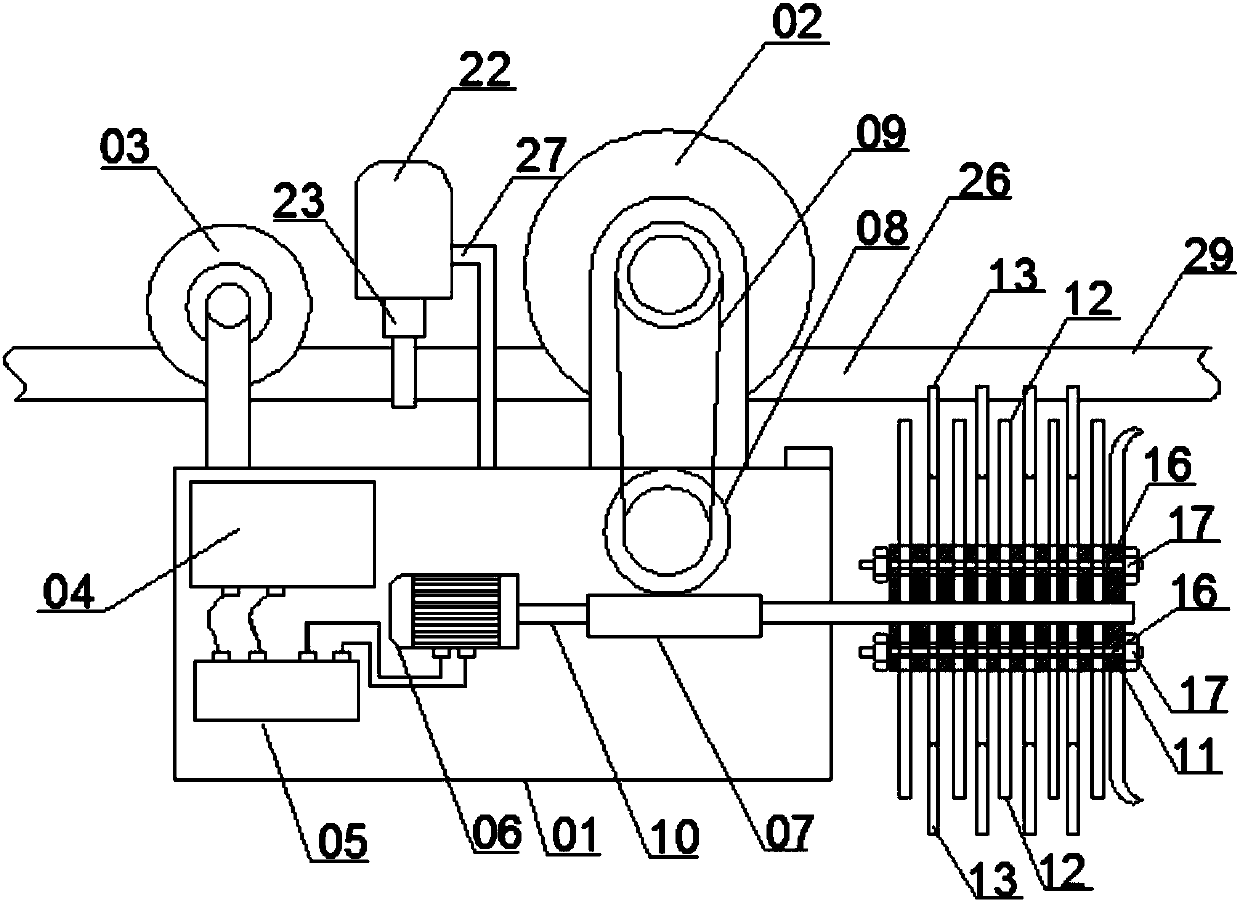
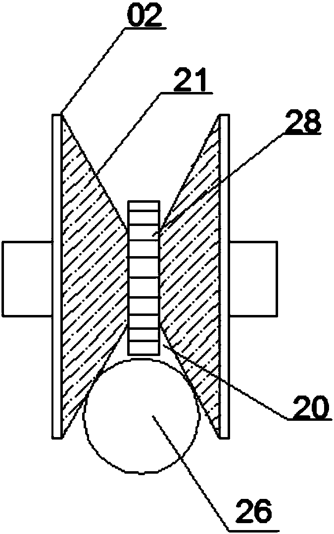
[0033] Please refer to figure 1 As shown, this embodiment provides an automatic deicing device for overhead high-voltage transmission lines, including a casing 01, a driving wheel 02 and a driven wheel 03 are installed on the casing 01, and the driving wheel 02 and the driven wheel 03 are provided with The circular pointed groove 20, the transmission line 26 is pressed in the pointed groove 20, and the whole deicing robot is suspended on the transmission line 26 through the driving wheel 02 and the driven wheel 03, and the robot is installed in the casing 01. The storage battery 04 and the controller 05 that provide power, the drive motor 06 and the turbine 08 worm 07 mechanism are arranged in the casing 01, the worm 07 is connected with the output shaft of the drive motor 06, the turbine 08 is arranged above the worm 07 and meshed with the worm 07, the turbine 08 is connected to the driving wheel 02 through the transmission belt 09. The front end of the worm 07 protrudes from...

Embodiment 2

[0046] Embodiment 2 is basically the same as Embodiment 1, the difference is that the steel knives 12 for hard hitting and the steel knives for soft hitting 13 on the rotating column are arranged in groups and staggered from the front end to the rear end of the rotating column, and each group is respectively arranged at On different levels, each group consists of 3 strip-shaped hard-hitting steel knives 12 or 3 strip-shaped soft-hitting steel knives 13, which are intersected at an angle of 120° on the same level. According to the characteristics of stable mechanical force, this can make the rotating body 10 reach a relative dynamic balance when the blade rotates to break the ice.


PUM


Abstract

The invention discloses an automatic deicing device for overhead high-voltage transmission lines, relates to the technical field of overhead transmission cable protection equipment, and solves the problem that the distance between the cutter heads of the existing deicing mechanism cannot be adjusted or can only be disassembled and assembled at the construction site. The ice breaking position of the blade can only be adjusted under the condition of the machine structure, which includes the casing, the driving wheel and the driven wheel are installed on the casing, the driving motor and the worm gear mechanism are arranged in the casing, and the front end of the worm protrudes from the casing and is connected to a The rotating body rotates with the rotation of the worm. The rotating body is equipped with a mechanical deicing mechanism. The mechanical deicing mechanism includes a rotating column and a plurality of blades uniformly arranged radially along the rotating column. The rotating column is equipped with a blade for adjusting the locking position of the blade. The locking mechanism, through the implementation of this technical solution, can effectively avoid the problem that the distance between the cutter head of the deicing mechanism cannot be adjusted or the ice breaking position of the blade can only be adjusted when the whole machine structure is disassembled at the construction site, and it is suitable for removing ice with different diameters. Overhead lines covered with ice.

Description

technical field [0001] The invention relates to the technical field of protection equipment for overhead power transmission cables, and more particularly relates to an automatic deicing device for overhead high-voltage power transmission lines. Background technique [0002] Icing of transmission lines in winter is one of the natural disasters of the power system. Due to the increased ice load on the conductors, it will cause certain mechanical damage to the conductors, iron towers and fittings. When the ice is severe, the wires will be disconnected, the towers will be inverted, the conductors will dance and flashover and trip, resulting in large-scale power outages. Because the accident occurred in the severe winter season, the mountain was blocked by heavy snow or the road was icy, which made the emergency repair conditions very difficult, resulting in a long-term power outage, which seriously threatened the safe and stable operation of the power grid and the reliability of...

Claims


Application Information

Patent Timeline
Patent Type & Authority Applications(China)
IPC IPC(8): H02G7/16B05C5/02
CPCH02G7/16B05C5/0241
Inventor 宋平
Owner 弘毅天承知识产权股份有限公司
Why Eureka
Try Eureka