Slow-starting circuit, power panel provided with slow-starting circuit, and service single board provided with slow-starting circuit

A slow-start circuit and slow-start technology, applied in electrical components, electronic switches, output power conversion devices, etc., can solve problems such as large inrush current and instantaneous stress, unstable socket connection, damage risk, etc., to speed up the discharge. speed, reducing the probability of damage, and improving reliability

Active Publication Date: 2018-03-06
ZTE CORP
View PDF8 Cites 5 Cited by
  • Summary
  • Abstract
  • Description
  • Claims
  • Application Information

AI Technical Summary

Problems solved by technology

[0003] Now commonly used slow start circuit see figure 1 , the input power supply part is easily connected to the socket unstable when it is just inserted into the socket or when the socket is replaced, resulting in rapid power-on after power-off at the input end. In this case, the large filter capacitor C2 at the output end discharges slowly, which will cause Charge C1 all the time, although the original intention of the triode VT1 is to discharge the power on C1 as soon as possible, because C1 is slowly discharged through the diode VD2, VT1 is not turned on at all, so C1 cannot discharge quickly, resulting in the slow start of the drive of the MOS transistor VT2 The voltage cannot quickly drop to 0 volts, so that in the case of fast startup again, the slow-start MOS tube cannot function as a slow-start, and is always in the on state or half-on state. The consequence of this is that if the slow-start MOS tube VT2 happens to be on When the input terminal is powered on again in the half-open state, the slow start MOS tube will generate a large inrush current and instantaneous stress, and there is a risk of damage

Method used


Image

  • Slow-starting circuit, power panel provided with slow-starting circuit, and service single board provided with slow-starting circuit
  • Slow-starting circuit, power panel provided with slow-starting circuit, and service single board provided with slow-starting circuit
  • Slow-starting circuit, power panel provided with slow-starting circuit, and service single board provided with slow-starting circuit

Examples


no. 1 example

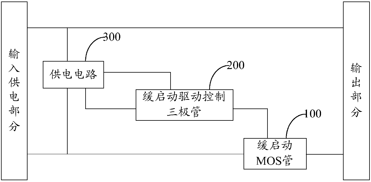
[0031] The first embodiment of the present invention is a slow start circuit, the slow start circuit is connected between the input power supply part and the output part, such as image 3 As shown, the slow start circuit includes the following components: a slow start MOS transistor 100, a slow start drive control transistor 200 and a power supply circuit 300, wherein,

[0032] The power supply circuit 300 supplies power to the slow-start drive control transistor 200 and determines the delay time of the slow-start drive control transistor 200 from off to on;

[0033] When the power supply input end is turned on, the power supply circuit 300 supplies power to the slow-start drive control transistor 200 and makes the slow-start drive control transistor 200 conduct after the delay time, and starts the slow-start MOS transistor 100 when the slow-start drive control transistor 200 is turned on. ;

[0034] Since the power input terminal is powered off, the power supply circuit 300 ...

no. 2 example

[0035] The second embodiment of the present invention is a slow start circuit, the slow start circuit is connected between the input power supply part and the output part, such as Figure 4 As shown, this embodiment is roughly the same as the first embodiment, the only difference is that this embodiment further defines an implementation of the power supply circuit:

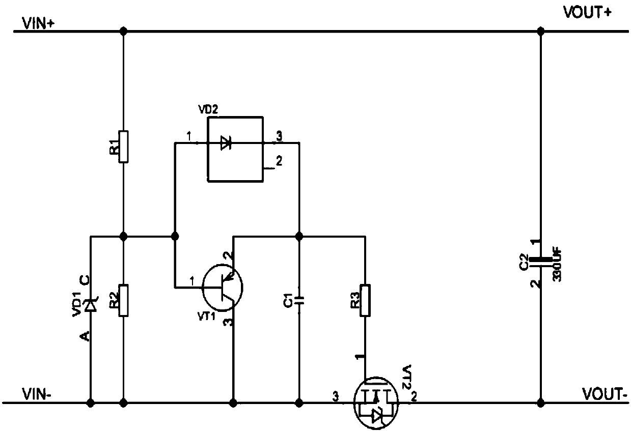
[0036] The power supply circuit 300 includes: a first power supply unit 301 and a second power supply unit 302, wherein the first power supply unit 301 supplies power to the emitter of the slow start drive control triode 200 and provides a slow start capacitor in a manner of resistive voltage division; The power supply unit 302 supplies power to the base of the slow-start drive control transistor 200 in the form of voltage division by a resistor and a voltage regulator; the collector of the slow-start drive control transistor 200 is connected to the gate of the slow-start MOS transistor 100 .

[0037] Specifically...

no. 3 example

[0040] The third embodiment of the present invention is a slow start circuit. The slow start circuit is connected between the input power supply part and the output part. This embodiment is roughly the same as the second embodiment. Some preferred implementations are provided on the basis of examples:

[0041] Preferably, the slow start circuit of this embodiment further includes: a current limiting resistor connected between the collector of the triode and the gate of the slow start MOS transistor to prevent the slow start MOS transistor from Gate overcharge voltage.

[0042] Preferably, the slow start circuit of this embodiment further includes: connected between the collector of the triode and the source or drain of the slow start MOS transistor and used to adjust the gate of the slow start MOS transistor Potential voltage divider resistors.

[0043] Preferably, the slow-start circuit in this embodiment further includes: a voltage regulator transistor connected between th...


PUM


Abstract

The invention provides a slow-starting circuit, a power panel provided with the slow-starting circuit, and a service single board provided with the slow-starting circuit. The slow-starting circuit comprises a slow-starting MOS tube, a slow-starting driving control triode and a power supply circuit. The power supply circuit supplies power to the slow-starting driving control triode so as to determine the delay duration of the triode from the turn-off to the turn-on of the triode. From the power-on moment of a power input end, the power supply circuit supplies power to the triode and the triodeis turned on after the above delay duration. When the triode is turned on, the slow-starting MOS tube is turned on. From the power-off moment of the power input end, the power supply circuit stops supplying power to the triode. The triode is therefore turned off and then the slow-starting MOS tube is turned off. According to the invention, the discharge speed of the grid of the slow-starting MOS tube is accelerated. Meanwhile, the risk caused by the fact that a traditional slow-starting circuit is frequently turned on and off can be solved.

Description

technical field [0001] The invention relates to the technical field of communication equipment power supply, in particular to a slow start circuit, a power board and a service board including the circuit. Background technique [0002] In the case where the slow start circuit is set on the service board of the communication device, the communication device requires the replacement or restart of the service board without powering off the whole machine, which requires the power supply circuit of the device port to support hot swapping Function; when the slow start circuit is set on the power board of the communication equipment, the power supply circuit of the power board is also required to support the hot swap function. [0003] Now commonly used slow start circuit see figure 1 , the input power supply part is easily connected to the socket unstable when it is just inserted into the socket or when the socket is replaced, resulting in rapid power-on after power-off at the inp...

Claims


Application Information

Patent Timeline
Patent Type & Authority Applications(China)
IPC IPC(8): H02M1/36H02M1/32
CPCH02M1/32H02M1/36H03K17/28
Inventor 王佩佩付强潘超蒋思东
Owner ZTE CORP
Why Eureka
Try Eureka