Optical element arrangements for varying beam parameter product in laser delivery systems

A technology of optical components, light beams, applied in the field of laser systems

Active Publication Date: 2018-03-06
PANASONIC OF NORTH AMERICA +1
View PDF41 Cites 3 Cited by
  • Summary
  • Abstract
  • Description
  • Claims
  • Application Information

AI Technical Summary

Problems solved by technology

In order to make such a change in the BPP of a laser system, the output optics or fiber must often be interchanged and/or realigned with othe...

Method used


Image

  • Optical element arrangements for varying beam parameter product in laser delivery systems
  • Optical element arrangements for varying beam parameter product in laser delivery systems
  • Optical element arrangements for varying beam parameter product in laser delivery systems

Examples


Embodiment Construction

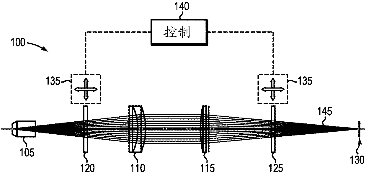
[0057] figure 1 Depicted is a schematic diagram of a laser beam delivery system 100 including beam steering optics according to an embodiment of the invention. In various embodiments, the laser beam delivery system 100 may be disposed within a laser-based cutting or welding head, for example. Beam delivery system 100 is characterized by connection to a laser generation system (e.g. not in figure 1 Beam delivery fiber terminating at fiber end cap 105 , collimating lens 110 , focusing lens 115 , and optical element 120 between end cap 105 and collimating lens 110 of the remainder of the WBC laser system shown in . In various implementations, the optical element 120 is positioned close to the fiber end cap 105 to minimize the size of the light beam impinging on the optical element 120 . Refraction of smaller beams can be performed using optics with smaller geometry and can change the output profile with higher sensitivity. figure 1 Also depicted is an optional second optica...


PUM


Abstract

In various embodiments, laser delivery systems feature one or more optical elements for receiving a radiation beam and altering the spatial power distribution thereof, a lens manipulation system for changing a position of at least one optical element within the path of the radiation beam, and a controller for controlling the lens manipulation system to achieve a target altered spatial power distribution on a workpiece.

Description

[0001] related application [0002] This application claims the benefit of and priority to US Provisional Patent Application No. 62 / 183,210, filed June 23, 2015, the entire disclosure of which is hereby incorporated by reference. technical field [0003] In various embodiments, the present invention relates to laser systems, particularly laser systems with controllable beam parameter products. Background technique [0004] High power laser systems are used in many different applications such as welding, cutting, drilling and material handling. Such laser systems typically include a laser emitter from which laser light is coupled into an optical fiber (or simply "fiber") and an optical system that focuses the laser light from the fiber onto the workpiece to be processed. Optical systems are generally designed to produce the highest quality laser beam or, equivalently, the beam with the lowest beam parameter product (BPP). BPP is the product of the divergence angle (half an...

Claims


Application Information

Patent Timeline
IPC IPC(8): G02B27/10G02B27/09G02B7/00
CPCG02B27/1086G02B27/0927G02B27/30G02B27/0961G02B27/0944G02B19/0057G02B7/005B23K26/064
Inventor 陈斌周望龙P·塔耶巴提F·维拉里尔-绍塞多
Owner PANASONIC OF NORTH AMERICA
Why Eureka
Try Eureka