Magnetic resonance imaging method and device

A magnetic resonance imaging and magnetic resonance imaging technology, applied in medical imaging, medical science, sensors, etc., can solve the problems of increased radio frequency pulse energy deposition, too large time interval setting, insufficient blood flow suppression, etc., to avoid blood vessel pulsation Artifacts, reduced number of applications, effects of suppressing interference

Active Publication Date: 2018-03-09
SHANGHAI UNITED IMAGING HEALTHCARE
View PDF5 Cites 16 Cited by
  • Summary
  • Abstract
  • Description
  • Claims
  • Application Information

AI Technical Summary

Problems solved by technology

However, applying too many saturation pulses during the imaging process will significantly prolong the scan time and increase the RF pulse energy deposition
On the other hand, if the time interval between adjacent saturation pulses is too large, blood flow suppression will be insufficient.

Method used


Image

  • Magnetic resonance imaging method and device
  • Magnetic resonance imaging method and device
  • Magnetic resonance imaging method and device

Examples


Embodiment 1

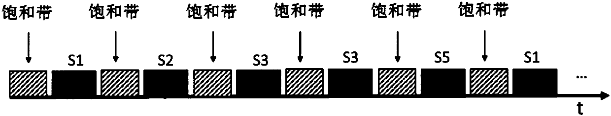
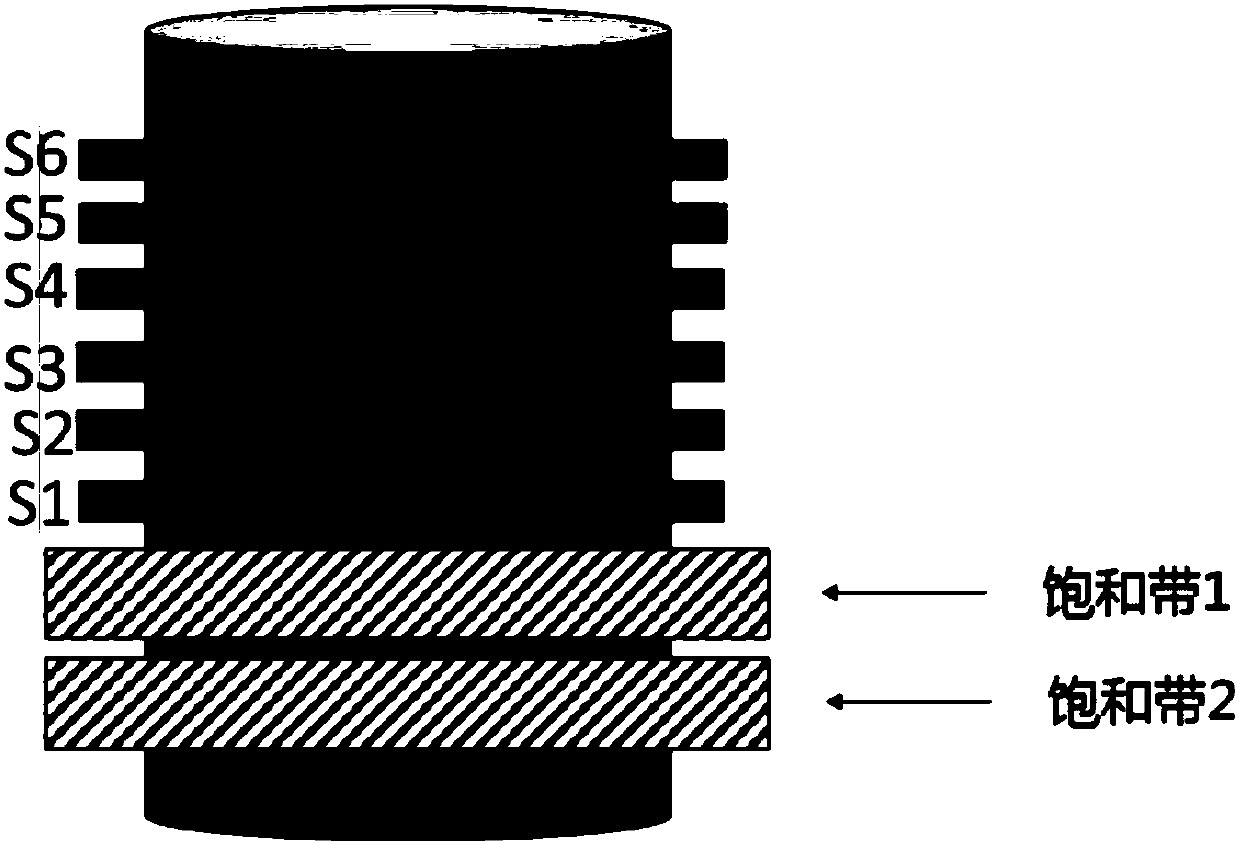
[0052] The scanning sequence may include two saturation pulses and a set of excitation radio frequency pulses, and the two saturation pulses are applied simultaneously before the set of excitation radio frequency pulses. Such as figure 2 As shown, the target area of ​​the subject is divided into six consecutive layers S1, S2, S3, S4, S5, and S6 in spatial position, and the saturation zone 1 and saturation zone 2 are set on the same side of the target area (a side), and the direction in which the saturation pulse is applied to the two saturation bands is along the direction of blood flow. Multiple (two) saturation pulses (sequences) can be applied to the two saturation zones, and each level is correspondingly excited by an excitation radio frequency pulse, and the excitation radio frequency pulse can excite six levels of the target area, and then the corresponding K-space data is collected. According to the preset distance threshold of the scan, the saturation band 1 and the ...

Embodiment 2

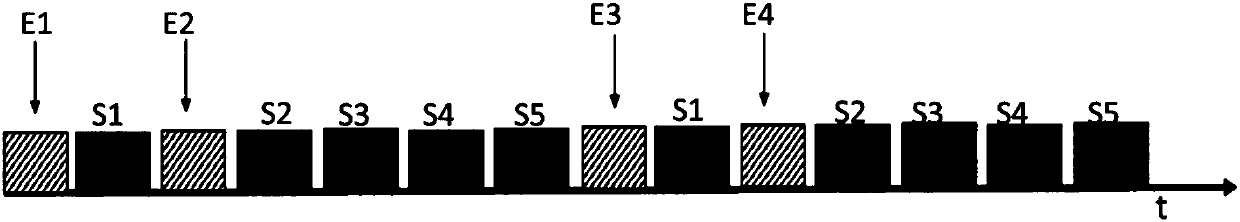
[0056] saturation band such as figure 2As shown, it is set on the same side of the target area (not shown), and the number of saturation bands is two. The difference from Embodiment 1 lies in the number of slices and the number of scans. The scan includes the first saturation pulse (sequence) E1, the second saturation pulse (sequence) E2 and a group of excitation radio frequency pulses (sequence), wherein a group of excitation radio frequency pulses includes the first excitation radio frequency pulse (sequence), the second excitation radio frequency pulse (sequence) and the third excitation RF pulse (sequence), the first saturation pulse E1 is applied before the first excitation RF pulse, and the second saturation pulse E2 is applied before the second excitation RF pulse. Furthermore, the target area can be divided into multiple groups of layers, the saturation pulse includes a first saturation pulse and a second saturation pulse, and the number of excitation radiofrequency p...

Embodiment 3

[0066] Such as Figure 4 As shown, the target area of ​​the subject is divided into six consecutive layers S1, S2, S3, S4, S5, and S6 in spatial position, and two saturation bands (saturation band 1 and saturation band 2) are respectively set in the target area On both sides, the direction of the saturation pulse applied on the saturation band is the same or opposite, which can be determined according to the direction of the blood flow to be suppressed or the direction of the chemical shift of the fat signal generated by the radio frequency pulse. A set of excitation radio frequency pulses in the scanning sequence includes multiple pulse sequences, and each layer corresponds to excitation radio frequency pulses, and the excitation radio frequency pulses can excite six layers of the target area, and then collect the corresponding K-space data. According to the preset distance threshold, the saturation bands 1 and 2 are respectively set on both sides (ends) of the target area. ...


PUM


Abstract

The invention discloses a magnetic resonance imaging method. The magnetic resonance imaging method comprises the steps that a scanning sequence is adopted to excite a target zone of a subject, K spacedata of the target zone is acquired, and the K space data is utilized to reestablish a magnetic resonance image, wherein the scanning sequence includes multiple saturated pulses and multiple radio frequency exciting pulses, the multiple radio frequency exciting pulses are utilized to excite multiple layers of the target zone, and multiple layers of K space data of the target zone are acquired, the target zone includes multiple continuously distributed layers, and one or more saturated zones are arranged on the outer sides of the multiple layers; saturated pulses are exerted on the saturated zones, and the saturated pulse exerting sequence is determined according to the distances between saturated zones and the multiple layers. The saturated pulses are exerted at non-equal time intervals,the saturated pulse exerting frequency can be effectively reduced, radio frequency energy absorption can be reduced, and scanning time is shortened. In addition, the invention also provides a magneticresonance imaging device.

Description

【Technical field】 [0001] The invention relates to the technical field of magnetic resonance imaging for medical diagnosis, in particular to a magnetic resonance imaging method and device capable of effectively suppressing blood flow signals. 【Background technique】 [0002] Magnetic resonance imaging is a medical imaging diagnostic technology that mainly uses the nuclear magnetic resonance phenomenon of a certain nucleus in human tissue, and processes the radio frequency signal obtained by a computer to reconstruct a certain level of the human body. Because of its multi-function, multi-parameter, multi-plane imaging and high soft tissue resolution, this imaging technology is widely used in the diagnosis of diseases. A typical MRI system includes the following components: magnets, gradient coils, RF transmit coils, RF receive coils, and signal processing and image reconstruction units. The imaging process is roughly as follows: the spin of the hydrogen nucleus in the human bo...

Claims


Application Information

Patent Timeline
Patent Type & Authority Applications(China)
IPC IPC(8): A61B5/026A61B5/055
CPCA61B5/0263A61B5/055A61B5/7207A61B2576/00
Inventor 李兆鹏李国斌王超洪
Owner SHANGHAI UNITED IMAGING HEALTHCARE
Why Eureka
Try Eureka