Displacement configuration of range hood and range hood
A technology of oil discharge structure and range hood, which is applied in the field of kitchen appliances, can solve the problems of flowing to the lower end of the network disk, entering the range hood shell, secondary pollution, etc., and achieve the effect of prolonging the working life, improving the service life, and large kinetic energy
- Summary
- Abstract
- Description
- Claims
- Application Information
AI Technical Summary
Problems solved by technology
Method used
Image
Examples
Embodiment 1
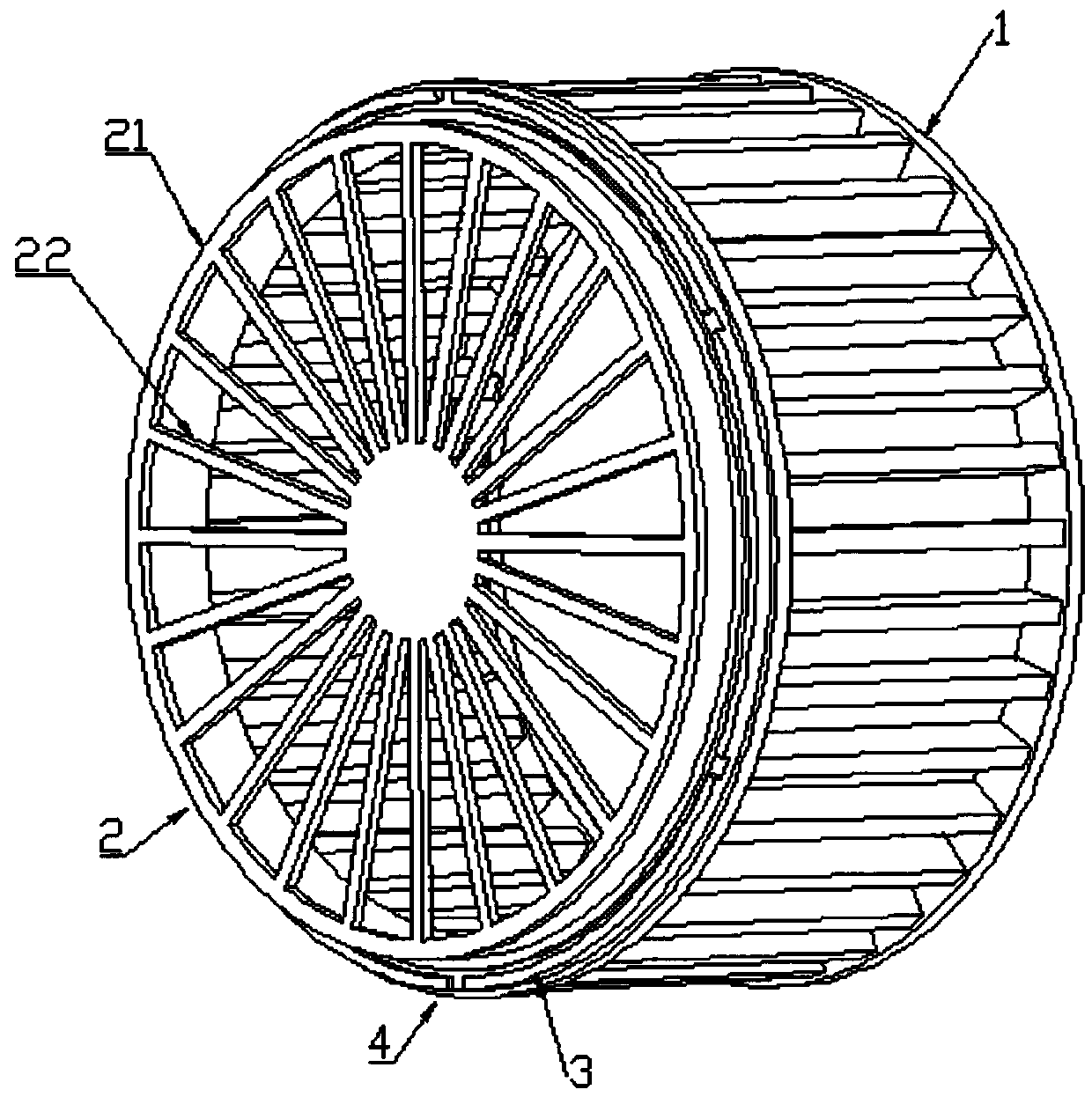
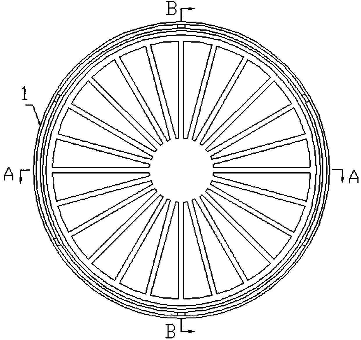
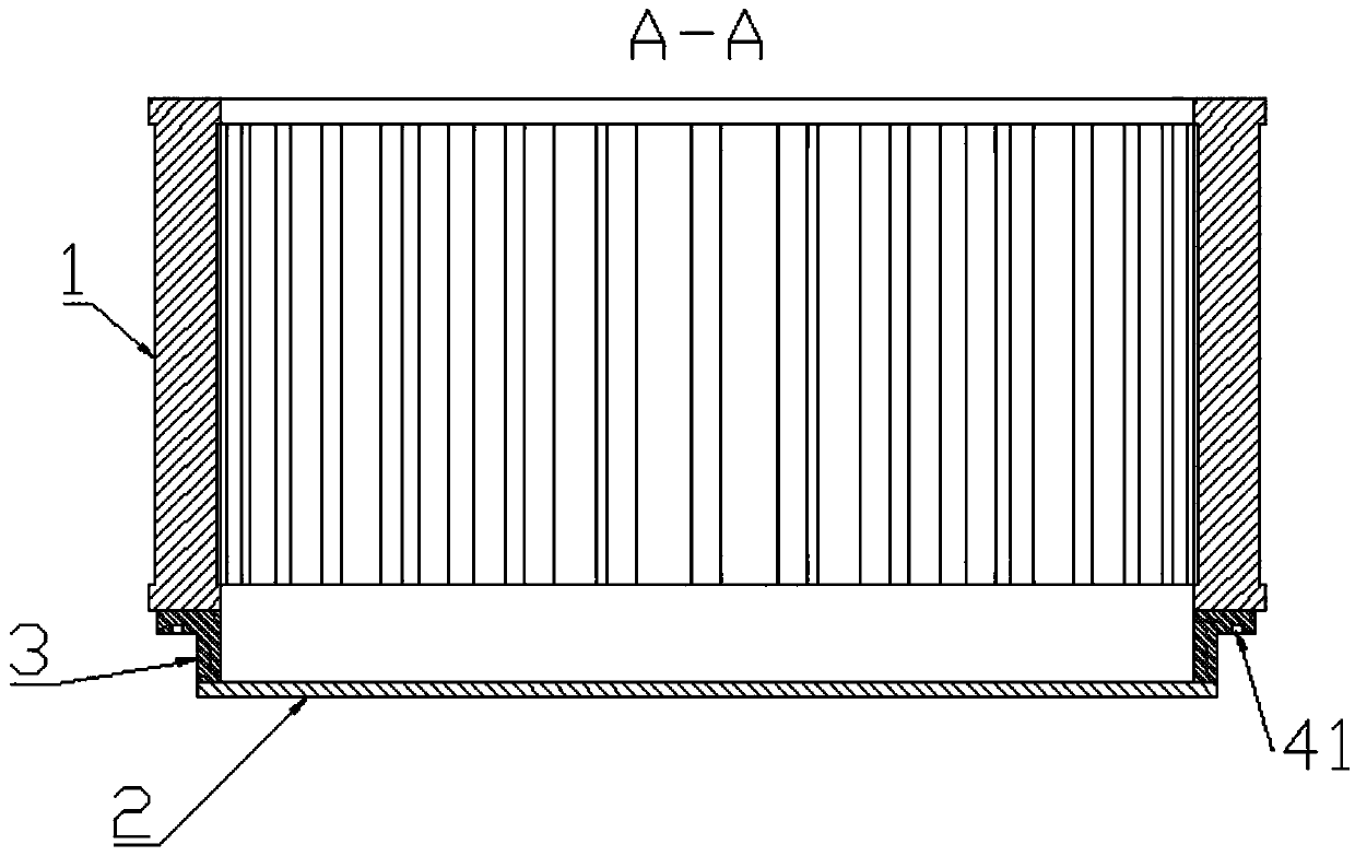
[0039] like Figure 1-4 As shown, in order to discharge the oil droplets intercepted on the grid plate 2 in a more regular manner, the technical solution adopted in this embodiment is that the oil discharge structure of the present invention also includes an annular connecting piece 3, on the connecting piece 3 Also be provided with the oil guide structure 4 that surrounds mesh wire 22 in a circle, described oil guide structure 4 comprises oil guide groove 41 and is arranged on the side of oil guide groove 41 far away from grid disk 2 axle centers and is used for the oil in oil guide groove 41 discharges. There are four oil discharge ports 42, and the oil discharge ports 42 are evenly distributed along the circumferential direction of the grid plate 2. The outer peripheral side of the mesh disk 2 is connected to the inner peripheral side of the front end of the impeller 1 through a connecting piece 3 . The oil guide groove 41 is an annular groove arranged on the end face of t...
Embodiment 2
[0048] like Figure 5-6 As shown, the difference between this embodiment and Embodiment 1 is that the oil discharge port 42 is an oblique outlet, specifically, the oil discharge port 42 is formed at a certain angle from the bottom surface of the oil guide groove 41 along the direction away from the axis of the mesh disk 2. Obliquely penetrating through the side wall of the oil guide groove 41 , setting the oil outlet 42 obliquely can allow more oil droplets to collect in the oil guide groove 41 , and enable the oil droplets to be discharged from a position farther away from the impeller 1 .
Embodiment 3
[0050] like Figure 7-8 As shown, in order to discharge the oil droplets intercepted on the network disk 2 in a relatively regular manner, the technical solution adopted in this embodiment is that an oil guide structure 4 is also provided on the network disk 2, and the oil guide structure 4 is arranged along the The radial distribution of the mesh disk 2 is on the periphery of the mesh wire 22, and the oil guide structure 4 includes an oil guide groove 41 and a plurality of holes arranged on the side of the oil guide groove 41 away from the axis of the mesh disk 2 for discharging the oil in the oil guide groove 41. There are four oil discharge ports 42, and the oil discharge ports 42 are evenly distributed along the circumferential direction of the grid plate 2.
[0051] Specifically, the oil guide groove 41 is an annular groove arranged on the outer edge of the grid plate 2 and recessed toward the impeller 1 along the axial direction of the grid plate 2, and the oil discharge...
PUM
 Abstract
Description
Claims
Application Information
 - R&D
- Intellectual Property
- Life Sciences
- Materials
- Tech Scout
- Unparalleled Data Quality
- Higher Quality Content
- 60% Fewer Hallucinations
Browse by: Latest US Patents, China's latest patents, Technical Efficacy Thesaurus, Application Domain, Technology Topic, Popular Technical Reports.
© 2025 PatSnap. All rights reserved.Legal|Privacy policy|Modern Slavery Act Transparency Statement|Sitemap|About US| Contact US: help@patsnap.com


