
Coil electronic component and antenna

A technology of electronic components and coils, which is applied to coils, electrical components, loop antennas with ferromagnetic material cores, etc., can solve the problems of increasing the recognition angle, increasing the DC resistance characteristics, and being unable to diversify the characteristics of the magnetic core, so as to achieve improvement Reliability, Size Reduction Effects

Inactive Publication Date: 2018-03-09
WITS CO LTD
View PDF5 Cites 2 Cited by
  • Summary
  • Abstract
  • Description
  • Claims
  • Application Information

AI Technical Summary

Problems solved by technology

In order to increase the inductance, the number of turns of the coil needs to be increased, however, since the size of electronic components is in the trend of miniaturization, the number of turns cannot be increased blindly
In addition, in the case of a main antenna as an example of a coil electronic component, since it is constituted by a loop antenna in the form of an air-core coil, it is necessary to increase the number of turns of the coil in order to increase the inductance. , thus, resulting in an increase in the characteristic of the DC resistance (Rdc)
In addition, the sub (sub) antenna will also form a magnetic field mainly along the direction perpendicular to the coil, so there is a limitation in increasing the recognition angle
[0003] In this case, the following Patent Document 1 discloses an electronic component in which a plurality of coils are wound on a magnetic core laminated with a plurality of thin metal plates so that the respective coils are connected in parallel. The problem of diversification of the characteristics of the magnetic core

Method used


Image

  • Coil electronic component and antenna
  • Coil electronic component and antenna
  • Coil electronic component and antenna

Examples


Embodiment Construction

[0026] Hereinafter, embodiments of the present disclosure will be described with reference to specific embodiments and the accompanying drawings. However, the embodiments of the present disclosure can be modified into various other forms, and the scope of the present disclosure is not limited to the embodiments described below. Furthermore, the purpose of providing the embodiments of the present disclosure is to more completely explain the present disclosure to those skilled in the art. Therefore, the shapes, sizes, and the like of elements in the drawings may be exaggerated for clearer description, and elements denoted by the same reference numerals in the drawings are the same elements.

[0027] In addition, in the drawings, in order to more clearly describe the present disclosure, parts irrelevant to the description are omitted, and the thicknesses are shown enlarged in order to more clearly show a plurality of layers and regions, and within the scope of the same idea Comp...


PUM


Abstract

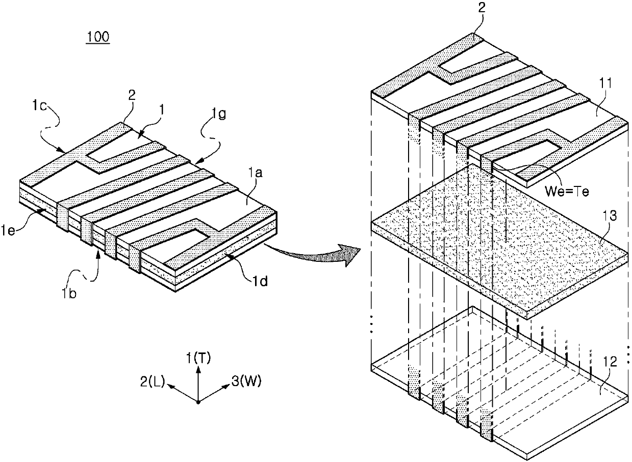
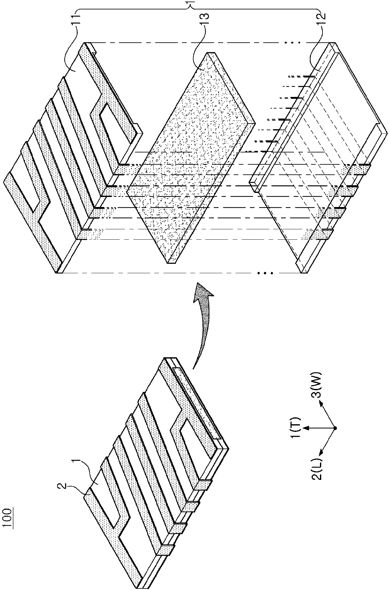
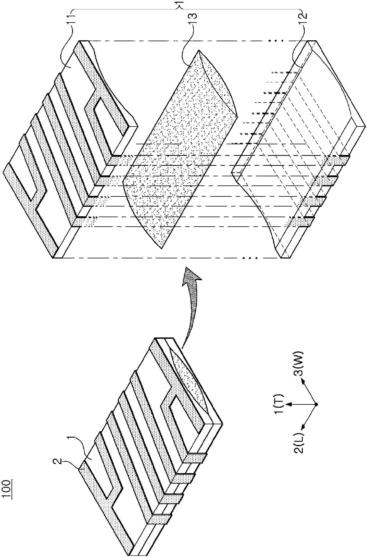
The invention discloses a coil electronic component and antenna, wherein the electronic component includes a main body having a magnetic characteristic and a coil arranged on the external surface of the main body, the main body contains a plurality of sheets, and the uppermost sheet and the lowermost sheet among the sheets are protective sheets; and the antenna contains the main body in the coil electronic component as a core part and contains the coil in the coil electronic component as a coil part,, and is arranged in the position of a main antenna or the position of a sub-antenna.

Description

technical field [0001] The present disclosure relates to a coil electronic component and an antenna, and more particularly to a coil electronic component and an antenna that contain a magnetic material in a main body, and the main body includes a plurality of sheets, and has a structure in which a coil is wound on an outer surface of the main body . Background technique [0002] Generally, if a current flows through a coil, a magnetic field is generated in a direction perpendicular to the coil, thereby having an inductance. In order to increase the inductance, the number of turns of the coil needs to be increased, however, since the size of electronic components is in the trend of miniaturization, the number of turns cannot be increased blindly. In addition, in the case of a main antenna as an example of a coil electronic component, since it is constituted by a loop antenna in the form of an air-core coil, it is necessary to increase the number of turns of the coil in order...

Claims


Application Information

Patent Timeline
IPC IPC(8): H01F5/00H01Q7/06
CPCH01Q7/06H01F5/00H01Q1/38H01F2003/005H01F2005/027H01F5/003
Inventor 权纯光柳正基郑昌烈徐正旭金仁圭
Owner WITS CO LTD
Learn More