
Permanent magnet brushless motor

A permanent magnet brushless motor and rotor technology, applied in the direction of electrical components, electromechanical devices, magnetic circuit static parts, etc., can solve the problems of large DC impedance of the coil, large span of copper wire at the end of the stator, and waste of copper, etc. Achieve the effects of small noise and torque fluctuation, optimized armature diameter and high efficiency

Inactive Publication Date: 2018-03-09
徐州鸿润达机电有限公司
View PDF0 Cites 0 Cited by
  • Summary
  • Abstract
  • Description
  • Claims
  • Application Information

AI Technical Summary

Problems solved by technology

However, the eddy current loss of the fractional slot concentrated winding is relatively large, and it is not suitable for field weakening control. Although the fractional slot concentrated winding can reduce the "cogging effect", it is at the cost of sacrificing part of the efficiency of the motor. At the same time, the distributed winding permanent magnet brushless motor , the copper wire span at the end of the stator is relatively large, the DC resistance of the coil is large, the line loss increases, and the copper material is wasted seriously. Now the country calls for "energy saving, emission reduction, high efficiency and energy saving", so it is necessary to develop a permanent magnet non-conductor with high efficiency and high torque. brush motor

Method used


Image

  • Permanent magnet brushless motor
  • Permanent magnet brushless motor
  • Permanent magnet brushless motor

Examples


Embodiment

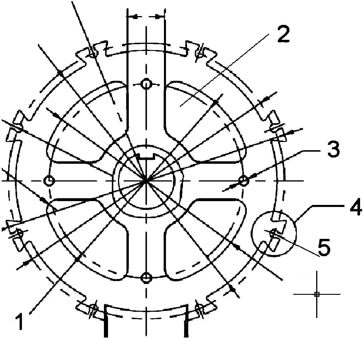
[0017] A permanent magnet brushless motor, comprising a motor housing, a rotor and a stator. The rotor is formed by superimposing rotor punching pieces with a diameter of 78mm. The stator is superimposed by stator punching pieces. The diameter is 120mm. The rotor punching piece is provided with a shaft hole 1 from the inside to the outside. The shaft hole diameter is 15mm, the heat dissipation hole 2, the rotor mounting hole 3 and the protruding teeth 4. The number of protruding teeth is 8, and the protruding teeth are 4. The distance between the two is 21mm, the center of the tooth 4 is also provided with a circular slot 5, the opening width of the circular slot is 1.5, and the diameter of the circular hole is 2.2mm. The stator punching piece is provided with rotor holes 6 in sequence from the inner to the outer ring, The diameter of the rotor hole is 79mm, the slot 7, the winding slot 8 and the stator mounting hole 9, and the width of the slot 7 is 1.67mm.

[0018] The said sha...


PUM


Abstract

The invention discloses a permanent magnet brushless motor, which includes a motor casing, a rotor and a stator, the rotor is formed by stacking rotor punches, and the stator is formed by stacking stator punches, characterized in that: The rotor punches are provided with shaft holes, heat dissipation holes, rotor mounting holes and 8 protruding teeth in sequence from the inside to the outside. The distance between the protruding teeth is 21mm, and there is a circular groove in the center of the protruding teeth. The stator punch The sheet is provided with rotor holes, tooth slots, winding slots and stator installation holes in sequence from the inner to the outer ring. The width of the slots is 1.67mm, which optimizes the armature diameter of the motor and the slot shape of the motor. slot and optimize the rotor pole arc coefficient and notch width, the stator buckle slot is changed from the original horizontal to vertical, and then the influence on the magnetic circuit of the motor is minimized, and the shape of the stator slot shoulder is changed to make the motor stator punch Sheet molds are more durable. Compared with the original motor, the designed motor has higher efficiency, lower temperature rise, and minimal noise and torque fluctuation.

Description

Technical field [0001] The invention relates to the field of motor manufacturing, in particular to a permanent magnet brushless motor. Background technique [0002] Most of the electric vehicle motors used in the early days used permanent magnet brushless motors, using fractional slots for concentrated winding. The fractional slot concentrated winding is mainly to solve the contradiction between the number of motor pole pairs and the number of motor slots, and to reduce torque ripple. , To make the electric vehicle run as smoothly as possible. However, the eddy current loss of the fractional-slot concentrated winding is relatively large, which is not suitable for field weakening control. Although the fractional-slot concentrated winding can reduce the "cogging effect", but at the expense of part of the efficiency of the motor, at the same time distributed winding permanent magnet brushless motor , The copper wire at the end of the stator has a large span, large DC impedance of t...

Claims


Application Information

Patent Timeline
IPC IPC(8): H02K29/03H02K1/24H02K1/16H02K1/32
CPCH02K29/03H02K1/16H02K1/24H02K1/32H02K2213/03
Inventor 宋雨桐
Owner 徐州鸿润达机电有限公司
Learn More