
Managing external interference in a wireless network

An external interference, wireless network technology, applied in wireless communications, data exchange networks, diversity/multi-antenna systems, etc., can solve the problems of interference, lack, and inability to quickly solve problems such as rapid spatial and temporal interference pattern changes

Active Publication Date: 2018-03-09
AIRSPAN NETWORKS INC PTSGE CORP
View PDF13 Cites 7 Cited by
  • Summary
  • Abstract
  • Description
  • Claims
  • Application Information

AI Technical Summary

Problems solved by technology

While it would be advantageous to provide wireless networks operating in license-exempt frequency bands, the lack of official regulation in such unlicensed bands due to their free availability means that wireless networks must be able to cope with wireless networks from unsolicited and uncoordinated wireless sources. co-channel and adjacent channel interference, and furthermore notwithstanding any initially well-planned deployment, if the wireless network is to be durable (in time) it must be able to rapidly adapt to static or dynamic, fixed or mobile radio communications from other sources quantity
One possible way to provide a wireless backhaul network in such an environment would be to use a contention-based protocol such as IEEE802.11 (WiFi), but then care must be taken to ensure that access does not occur by splitting the two air interfaces into separate Brings non-interfering backhaul, however other mobile devices or operators may nonetheless use the same spectrum causing significant interference
Although the wide availability of WiFi may represent a cheaper approach, WiFi cannot quickly account for rapid spatial and temporal interference pattern variations, making it less suitable in practice for the stringent requirements of real-time backhaul services

Method used


Image

  • Managing external interference in a wireless network
  • Managing external interference in a wireless network
  • Managing external interference in a wireless network

Examples


Embodiment Construction

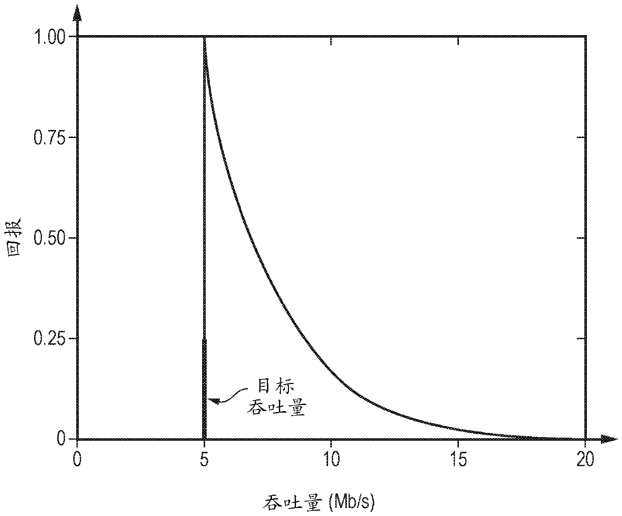
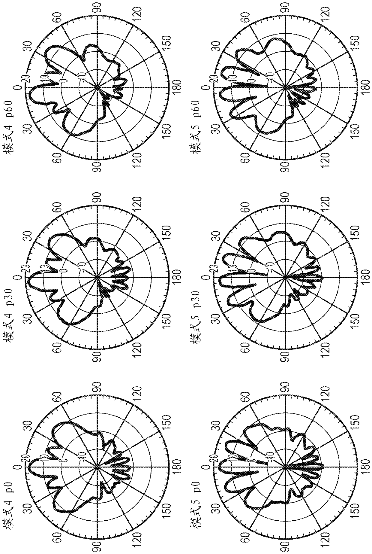
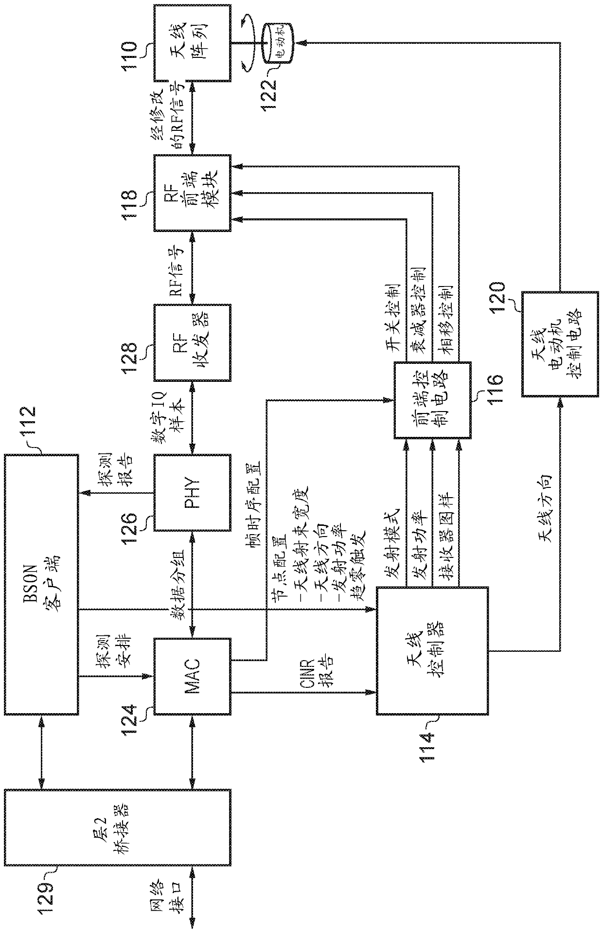
[0059] Some specific embodiments are now described with reference to the figures. figure 1 A multi-component network providing user equipment (UE) connectivity to a communication network such as the Internet is schematically illustrated. The item of user equipment 10-15 of this example communicates wirelessly with an LTE base station (enhanced Node B (eNB)). pay attention, figure 1 The LTE air interfaces shown in are examples only and the techniques are equally applicable to other suitable non-LTE air interfaces. Furthermore, although each access base station is shown communicating with a single item of end-user equipment for simplicity, it will be appreciated that such an access base station that actually forms a point-to-multipoint device enables many Items are able to communicate with individual access base stations. These eNB access sites then either have a direct wired connection (via IP protocol) to the communication infrastructure 20 in the case of 21 and 22 or to th...


PUM


Abstract

A method and corresponding apparatus are provided for configuring a wireless network comprising a plurality of nodes to mitigate effects of an external interference source. A subset of nodes of the plurality of nodes are configured to simultaneously participate in an external interference sampling process in which each node of the subset of nodes samples signals received by an antenna array of that node. A measurement report, comprising a signal source angle and a received signal strength, is received from a node. A location of the external interference source is firstly estimated using the measurement report received from the node. The external interference source is then characterised using the estimated location of the external interference source and the received signal strength to calculate for the external interference source at least one of: a source power; a beam width; an antenna bearing; and a front-to-back transmission ratio. Finally the plurality of nodes are configured tomitigate the effects of the external interference source in dependence on a result of the characterising step.

Description

technical field [0001] The present disclosure relates to wireless networks. More particularly, the present disclosure relates to external interference encountered in wireless networks. Background technique [0002] Wireless networks can be provided to serve a range of different functions, but one use of wireless networks is to perform backhaul in a communication network where user equipment devices (eg mobile phones) communicate with nodes of the wireless network, and the wireless network then enables these nodes Being able to communicate with other nodes of the wireless network, they are then connected (usually by wire) to the physical communication infrastructure and then continue to be connected to a wired communication network such as the Internet. There are many different use cases and different types of backhaul technologies available to mobile network operators, but in this context there is why it would be desirable to provide end nodes of wireless backhaul networks ...

Claims


Application Information

Patent Timeline
IPC IPC(8): H04W24/10H04L12/26H04L12/24H04B7/02H04W24/02H04W24/04
CPCH04W24/10H04B7/02H04L41/12H04L43/0888H04W24/02H04W24/04
Inventor M.利塞吉科A.洛戈塞蒂斯
Owner AIRSPAN NETWORKS INC PTSGE CORP
Learn More