
Microparticle remover and removal method for high-humidity dew-formed exhaust gas

A micro-particle and remover technology, applied in chemical instruments and methods, separation methods, dispersed particle filtration, etc., can solve the problems of high maintenance cost, increased filter bag resistance, large equipment investment, etc., and achieve low processing efficiency. Effect

Inactive Publication Date: 2018-03-13
杜传国
View PDF0 Cites 0 Cited by
  • Summary
  • Abstract
  • Description
  • Claims
  • Application Information

AI Technical Summary

Problems solved by technology

The occurrence of dew condensation, the accumulation of particulate matter will cause the bag hole to be blocked, and the dust layer will be slurried, so that the filter material will be sticky and cannot be removed, and the resistance of the filter bag will increase sharply until the air hole is blocked and the dust collector cannot operate.
[0005] 2. Although the wet electrostatic precipitator technology can effectively treat the high-humidity condensation flue gas to a certain extent, the process equipment is huge, the equipment investment is large, and the maintenance cost is high
The efficiency of the wet electrostatic precipitator is only about 70% in the actual operation process. In order to meet the current ultra-low emission standard of 5mg / m3, the dust concentration at the flue gas inlet should not exceed 18mg / m3. It is difficult to achieve "near-zero emission" Big

Method used


Image

  • Microparticle remover and removal method for high-humidity dew-formed exhaust gas
  • Microparticle remover and removal method for high-humidity dew-formed exhaust gas

Examples


Embodiment Construction

[0023] The preferred embodiments of the present invention will be described below in conjunction with the accompanying drawings. It should be understood that the preferred embodiments described here are only used to illustrate and explain the present invention, and are not intended to limit the present invention.

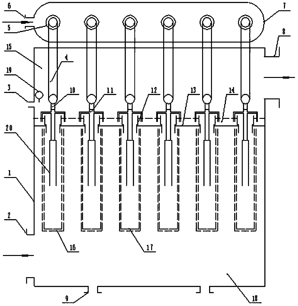
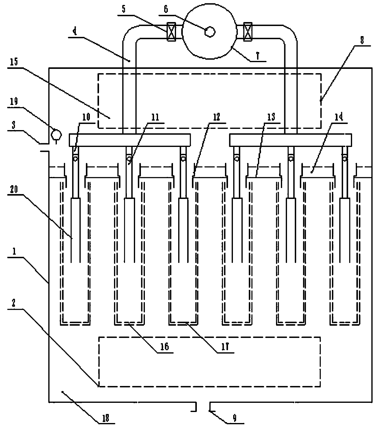
[0024] figure 1 and figure 2 Views of the internal structure in different directions for this patent application, such as figure 1 and figure 2 As shown, the housing 1 is included, and the housing 1 is provided with a clean air chamber 15 at the top and a lower air chamber 18 at the bottom of the clean air chamber 15. The lower air chamber 18 is provided with an air inlet 2, and the clean air chamber 15 is provided with a A partition 13 is arranged between the air port 8 , the lower air chamber 18 and the clean air chamber 15 .

[0025] The partition 13 is provided with a number of through holes, and the through holes are evenly arranged horizontally and vertic...


PUM


Abstract

The invention relates to a microparticle remover and a removal method for high-humidity dew-formed exhaust gas. The adopted technical scheme is that a gas purification chamber and a lower gas chamberare arranged from top to bottom in a casing; the lower gas chamber is provided with a gas inlet; the gas purification chamber is provided with a gas outlet; a partition is arranged between the lower gas chamber and the gas purification chamber; a plurality of gas passage seats for communicating the gas purification chamber with the lower gas chamber are arranged on the partition; filter barrels and frameworks are arranged below the gas passage seats; water distribution troughs are arranged on the partition; a water inlet and a liquid level sensor are arranged on the side wall of the gas purification chamber; a high-pressure gas tank is arranged outside the casing; the high-pressure gas tank is communicated with a gas fog uniform distributor through electromagnetic valves, high-pressure gaspipes, high-pressure gas branch pipes and gas fog generators. The microparticle remover makes use of high-pressure gas fog to thoroughly flush and wash microparticles such as soot gypsum fogdrops accumulated and adhered on the gas feeding surfaces of the filter barrels, so that by the technical scheme, the normal filter functions of the filter barrels can be completely guaranteed, and the problemthat a conventional dust remover cannot treat dew-formed exhaust gas or is low in treatment efficiency is solved.

Description

technical field [0001] The invention relates to a high-humidity dew condensation flue gas particle remover and a removal method, belonging to the field of environmental protection equipment. Background technique [0002] At present, the environmental problems caused by industrial production are becoming more and more prominent, and haze weather occurs from time to time, seriously affecting people's quality of life and health. The occurrence of smog is mainly caused by the incomplete removal of fine particles and other suspended matter contained in the flue gas when industrial flue gas is discharged. How to effectively and thoroughly remove the fine particles and other suspended matter in the flue gas is a The main means to prevent the occurrence of smog weather is also an urgent problem to be solved in the field of environmental protection technology. [0003] At present, the following technical solutions are mainly adopted in the prevention of dust pollution; [0004] 1. ...

Claims


Application Information

Patent Timeline
Patent Type & Authority Applications(China)
IPC IPC(8): B01D46/24B01D46/00
CPCB01D46/2411B01D46/72B01D46/71
Inventor 杜传国
Owner 杜传国
Learn More