
Automatic glue dispenser

A dispensing machine and automatic technology, applied in the field of dispensing machines, can solve problems such as low accuracy, error-prone, complicated manual dispensing operations, etc., and achieve the effect of convenient debugging and stable glue output

Inactive Publication Date: 2018-03-13
昆山冈村精密机械有限公司
View PDF8 Cites 0 Cited by
  • Summary
  • Abstract
  • Description
  • Claims
  • Application Information

AI Technical Summary

Problems solved by technology

[0002] Automatic dispensing machines have a wide influence in the industry. In industrial production, dispensing is required in many places, such as integrated circuits, semiconductor packaging, printed circuit boards, color LCD screens, electronic components (such as relays, speakers) , electronic components, auto parts, etc., traditional dispensing is realized by manual operation of workers. With the rapid development of automation technology, manual dispensing is far from meeting the requirements of industry. Manual dispensing has the advantages of complex operation and high speed. Slow, low precision, error-prone, and unable to operate complex graphics, let alone realize production automation and other shortcomings. The market requires a device with high speed, high efficiency and high precision, so a fully automatic dispensing robot appears.

Method used


Image

  • Automatic glue dispenser
  • Automatic glue dispenser
  • Automatic glue dispenser

Examples


Embodiment 1

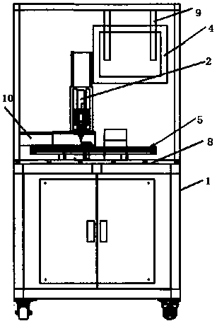
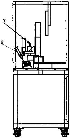
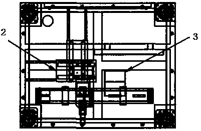
[0020] Such as figure 1 An automatic glue dispensing machine is shown, including a body 1, a four-axis arm 2, a UV lamp 3, a display screen 4, a belt flow channel 5, a glue dispenser 6, a CCD digital camera 7, a carrying platform 8, a connecting plate 9, Pressing plate 10, the middle position of the body body 1 is provided with a bearing platform 8, the bearing platform 8 is provided with a belt runner 5, and the belt runner 5 moves 20 cm every 6 seconds, and the belt runner is an induction motor belt Runner, the maximum moving speed of the motor: 100mm / sec, a pressure plate 10, a glue dispenser 6 and a UV lamp 3 are arranged above the belt flow channel 5, the irradiation power of the UV lamp is 30%, and the pressure plate 10 will reduce the pressure Press the product, the dispenser 6 is connected to the four-axis arm 2, the dispenser has the function of vacuum suction, and the glue output time of the dispenser is 30 seconds, the rear of the dispenser 6 is provided with CCD d...

Embodiment 2

[0035] Such as figure 1 An automatic glue dispensing machine is shown, including a body 1, a four-axis arm 2, a UV lamp 3, a display screen 4, a belt flow channel 5, a glue dispenser 6, a CCD digital camera 7, a carrying platform 8, a connecting plate 9, Pressing plate 10, the middle position of the body body 1 is provided with a bearing platform 8, the bearing platform 8 is provided with a belt runner 5, and the belt runner 5 moves 20cm every 6 seconds, and the belt runner is an induction motor belt Runner, the maximum moving speed of the motor: 100mm / sec, a pressure plate 10, a glue dispenser 6 and a UV lamp 3 are arranged above the belt flow channel 5, and the irradiation power of the UV lamp is 80%, and the pressure plate 10 will reduce the pressure Press the product, the dispenser 6 is connected to the four-axis arm 2, the dispenser has the function of vacuum suction, and the dispenser has a glue output time of 80 seconds, and the rear of the dispenser 6 is provided with ...


PUM


Abstract

The invention discloses an automatic glue dispenser. According to the automatic glue dispenser, a bearing platform is arranged at the middle part of a machine body main body; the bearing platform is provided with a belt runner; a pressing plate, a glue dispenser, and a UV lamp are arranged above the belt runner; the glue dispenser is connected with a four-axis arm; a CCD digital camera is arrangedbehind the glue dispenser; the bottom of the machine body main body is provided with universal wheels; the upper part of the machine body main body is connected with a display screen through a connecting plate. The automatic glue dispenser can be used for glue dispensing instead of manual operation, and is capable of realizing mechanization production.

Description

technical field [0001] The invention relates to a glue dispensing machine, in particular to an automatic glue dispensing machine. Background technique [0002] Automatic dispensing machines have a wide influence in the industry. In industrial production, dispensing is required in many places, such as integrated circuits, semiconductor packaging, printed circuit boards, color LCD screens, electronic components (such as relays, speakers) , electronic components, auto parts, etc., traditional dispensing is realized by manual operation of workers. With the rapid development of automation technology, manual dispensing is far from meeting the requirements of industry. Manual dispensing has the advantages of complex operation and high speed. Slow, low precision, error-prone, and unable to operate complex graphics, let alone realize production automation and other shortcomings. The market requires a device with high speed, high efficiency and high precision, so a fully automatic dis...

Claims


Application Information

Patent Timeline
IPC IPC(8): B05C5/02B05C11/10B05D3/06
CPCB05C5/02B05C11/10B05D3/067
Inventor 蔡承佑
Owner 昆山冈村精密机械有限公司
Learn More