
Automatic feeding device and method of industrial robot

An industrial robot and automatic feeding technology, which is applied in the direction of manipulators, manufacturing tools, program-controlled manipulators, etc., can solve problems such as loose joints of manipulator arms, damage, production troubles, etc., achieve accurate material positioning, avoid material slipping, and guarantee The effect of stable operation

Pending Publication Date: 2018-03-13
纳博特南京科技有限公司
View PDF6 Cites 10 Cited by
  • Summary
  • Abstract
  • Description
  • Claims
  • Application Information

AI Technical Summary

Problems solved by technology

[0009] The motion trajectory of the mechanical arm of the traditional industrial robot is relatively complicated when loading materials, and the stress on the joints of the mechanical arm is very different under different postures. Therefore, in the case of long-term use, the mechanical arm of the traditional industrial robot The connection between them is prone to loosening, which makes the positioning of the robotic arm inaccurate during the feeding process, and easily causes damage during product processing.
[0010] Traditional industrial robots often use the clamping method to grab materials. Due to long-term use, the grabbing end of the material is prone to loosening, and the material is not firmly grasped, which is easy to cause the material to fall. , damage, and bring unnecessary trouble to production

Method used


Image

  • Automatic feeding device and method of industrial robot
  • Automatic feeding device and method of industrial robot
  • Automatic feeding device and method of industrial robot

Examples


Embodiment Construction

[0033] The following will clearly and completely describe the technical solutions in the embodiments of the present invention with reference to the accompanying drawings in the embodiments of the present invention. Obviously, the described embodiments are only some, not all, embodiments of the present invention. Based on the embodiments of the present invention, all other embodiments obtained by persons of ordinary skill in the art without making creative efforts belong to the protection scope of the present invention.

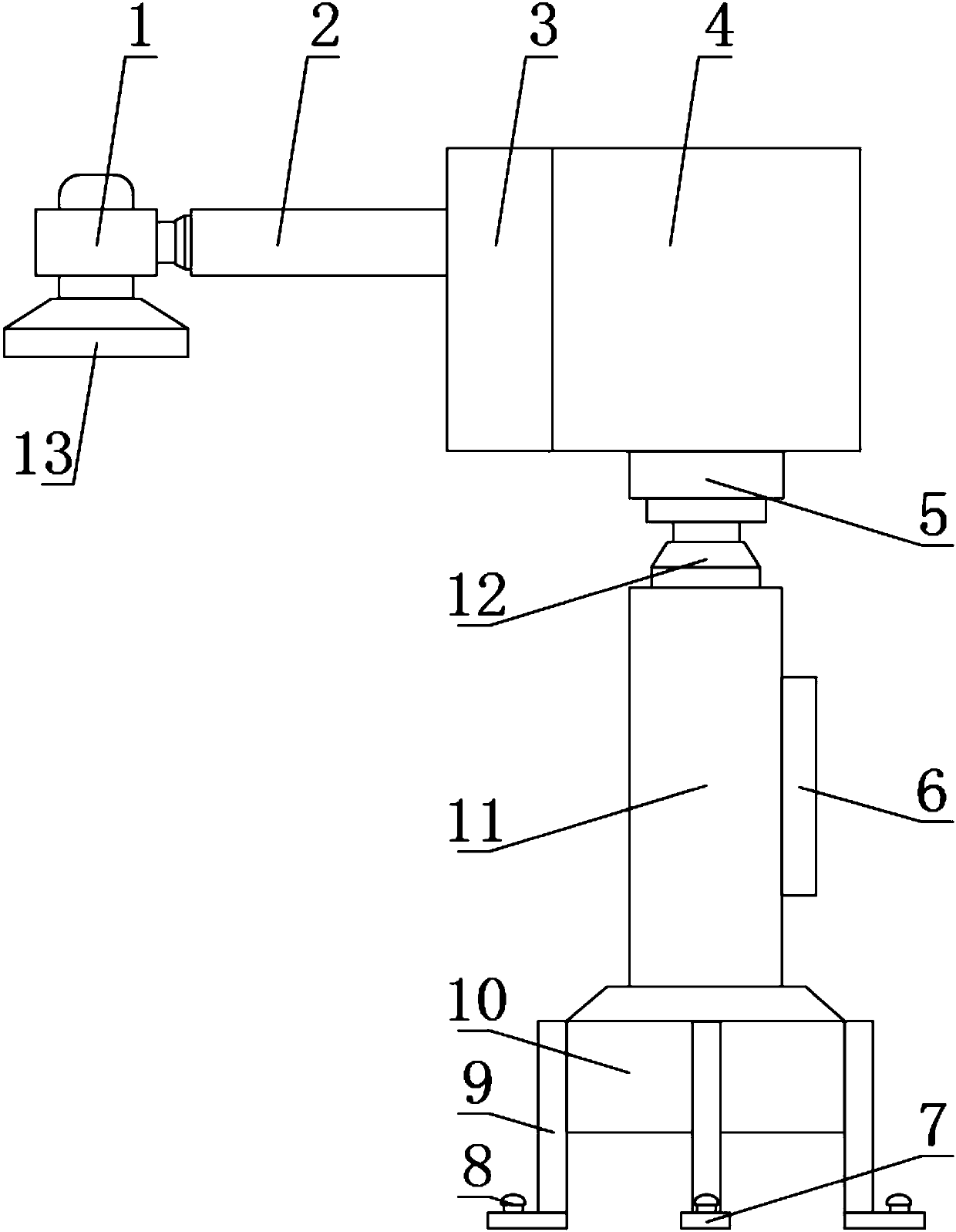
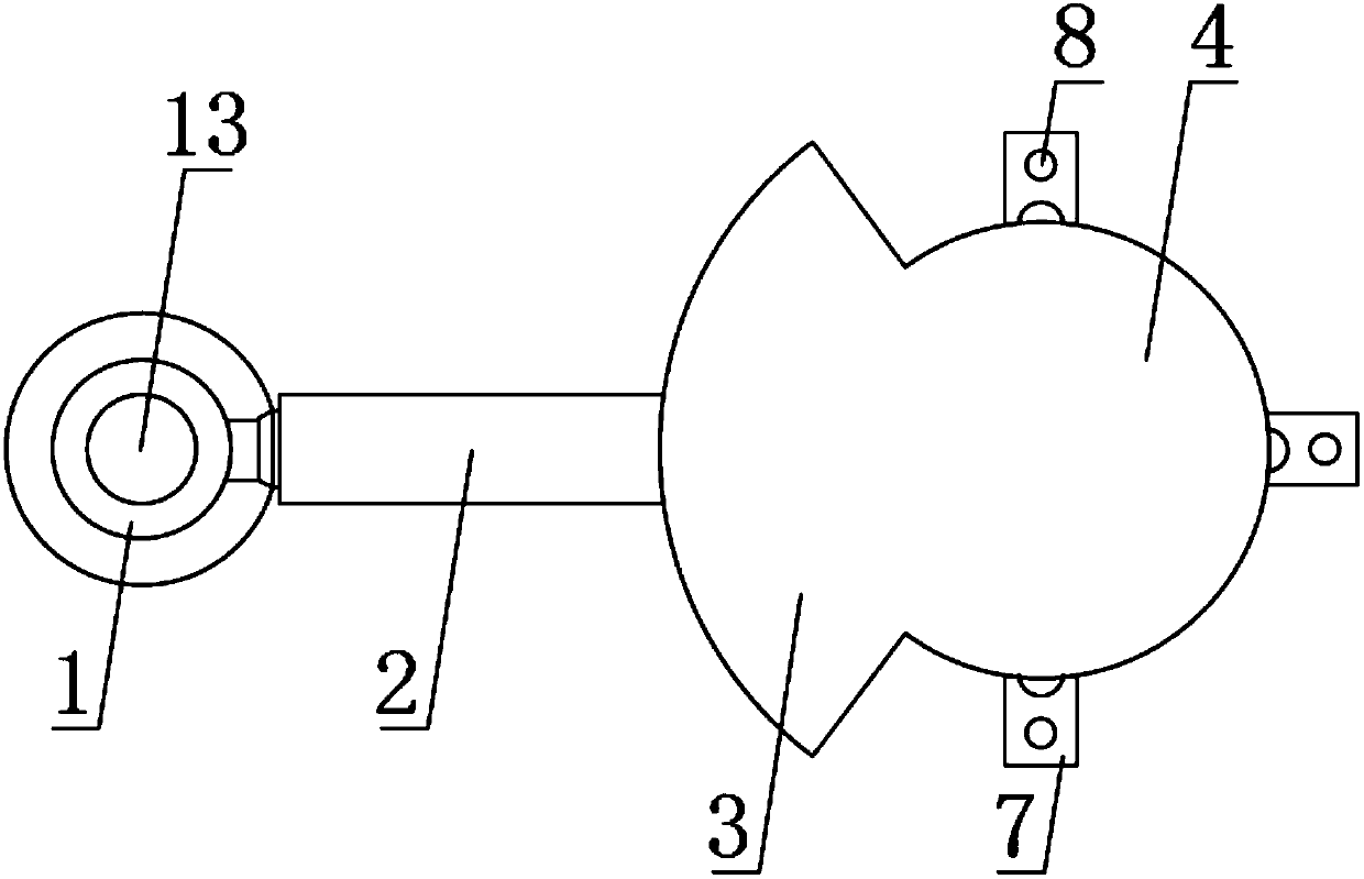
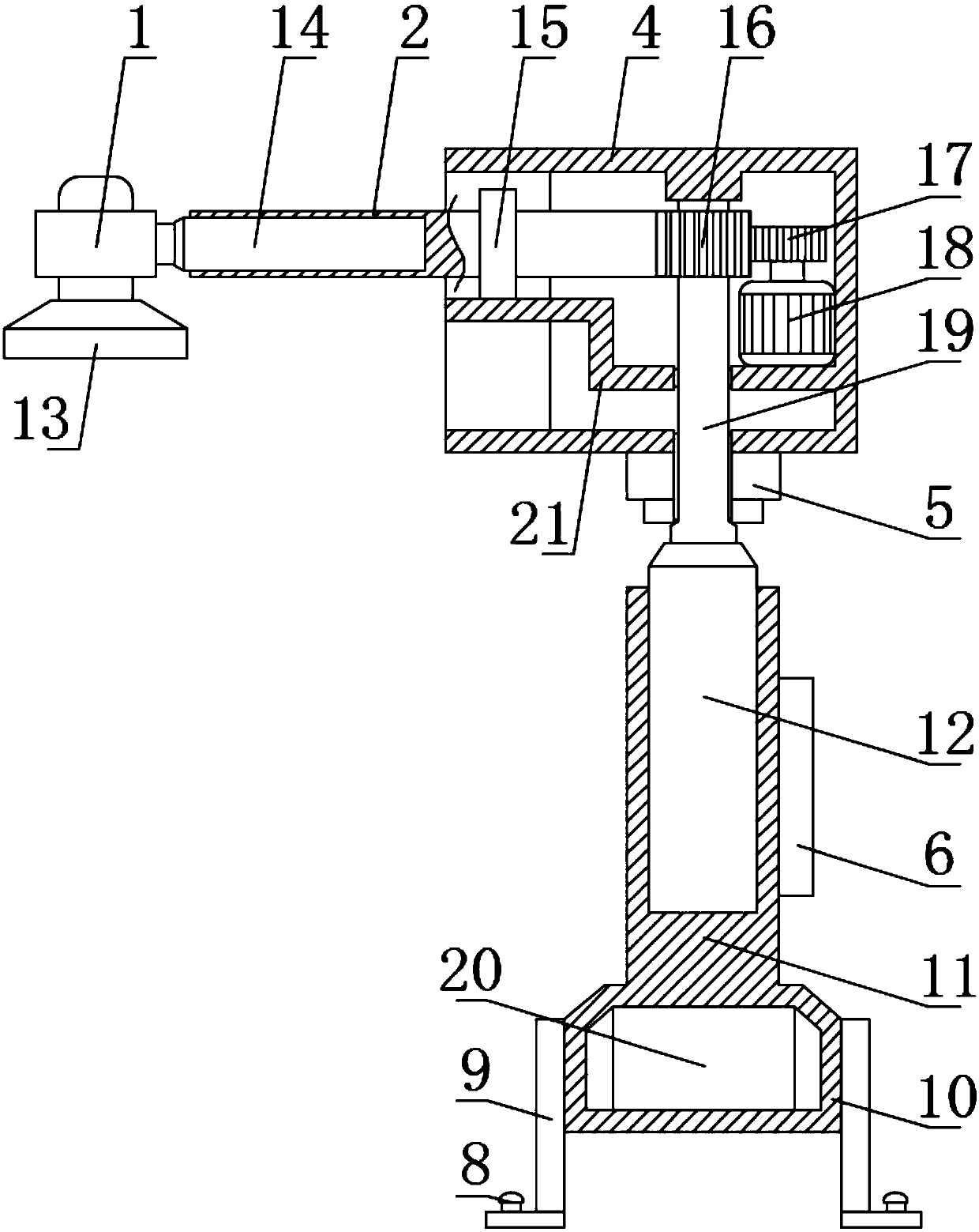
[0034] see Figure 1-4 , the present invention provides a technical solution: an automatic feeding device for an industrial robot, including a rotating rod 2, a rotating shell 4, a fixed base 10 and a support rod 11, the outer wall of the fixed base 10 is uniformly welded with four installation rods 9, The bottom of the installation rod 9 is fixedly welded with an installation base plate 7, and the middle part of the installation base plate 7 is threaded with ...


PUM


Abstract

The invention discloses an automatic feeding device of an industrial robot. The automatic feeding device comprises a rotating rod, a rotating shell, a fixed base and a supporting rod. Four mounting rods are evenly welded to the outer wall of the fixed base. A mounting bottom plate is fixedly welded to the bottom of each mounting rod, and a screw is mounted in the middle of each mounting bottom plate in a threaded manner. A power source is fixedly arranged in the fixed base. The supporting rod is fixedly welded to the upper surface of the fixed base. A control panel is fixedly mounted on the outer wall of one side of the supporting rod. A lifting hydraulic cylinder is fixedly mounted in the end, away from the fixed base, of the supporting rod. A fixed rod is fixedly welded to the power output end of the lifting hydraulic cylinder. According to the automatic feeding device, the outer portion of the rotating rod is fixedly connected with a bearing in a sleeved manner, the rotating rod isin sliding connection on a partition plate through the bearing, and therefore in the motion process of a mechanical arm, the stress condition of the connecting portion of the mechanical arm cannot change; and the situation that the connecting portion of the mechanical arm loosens due to stress changing is avoided, and material locating and feeding are more accurate.

Description

technical field [0001] The invention relates to the technical field of industrial robots, in particular to an automatic feeding device and method for industrial robots. Background technique [0002] An industrial robot is a multi-joint manipulator or a multi-degree-of-freedom machine device for the industrial field. It can perform work automatically and is a machine that realizes various functions by its own power and control capabilities. It can be commanded by humans or run according to pre-programmed programs. Modern industrial robots can also act according to the principles and programs formulated by artificial intelligence technology. [0003] The most notable features of industrial robots are as follows: [0004] (1) Programmable. A further development of production automation is flexible start-up. Industrial robots can be reprogrammed according to the changing needs of their working environment, so they can play a very good role in the flexible manufacturing proces...

Claims


Application Information

Patent Timeline
IPC IPC(8): B25J9/10B25J15/02
CPCB25J9/1035B25J15/0246
Inventor 甘亚光
Owner 纳博特南京科技有限公司
Learn More