Automatic laminator

A laminating machine, automatic technology, applied in packaging and other directions, can solve the problems of lack of fixed-point equidistant conveying and ejection of multiple products, inability to reach designated stations, low lamination efficiency, etc., to improve lamination accuracy and lamination efficiency, shorten the time The effect of filming time and reducing labor intensity

Active Publication Date: 2018-03-13
苏州才哲智能科技有限公司
View PDF10 Cites 8 Cited by
  • Summary
  • Abstract
  • Description
  • Claims
  • Application Information

AI Technical Summary

Problems solved by technology

This backward conveying method makes it take a long time for the product to go from one station to the next, resulting in a relatively low efficiency of film application
Even though some manufacturers currently use conveyor belts as the product film transfer mechanism, but because they do not have the functions of multi-product fixed-point equidistant delivery and ejection, the products cannot reach the designated station during the delivery process.

Method used


Image

  • Automatic laminator
  • Automatic laminator
  • Automatic laminator

Examples


Embodiment Construction

[0053] The present invention will be described in detail below with reference to the accompanying drawings and in combination with embodiments.

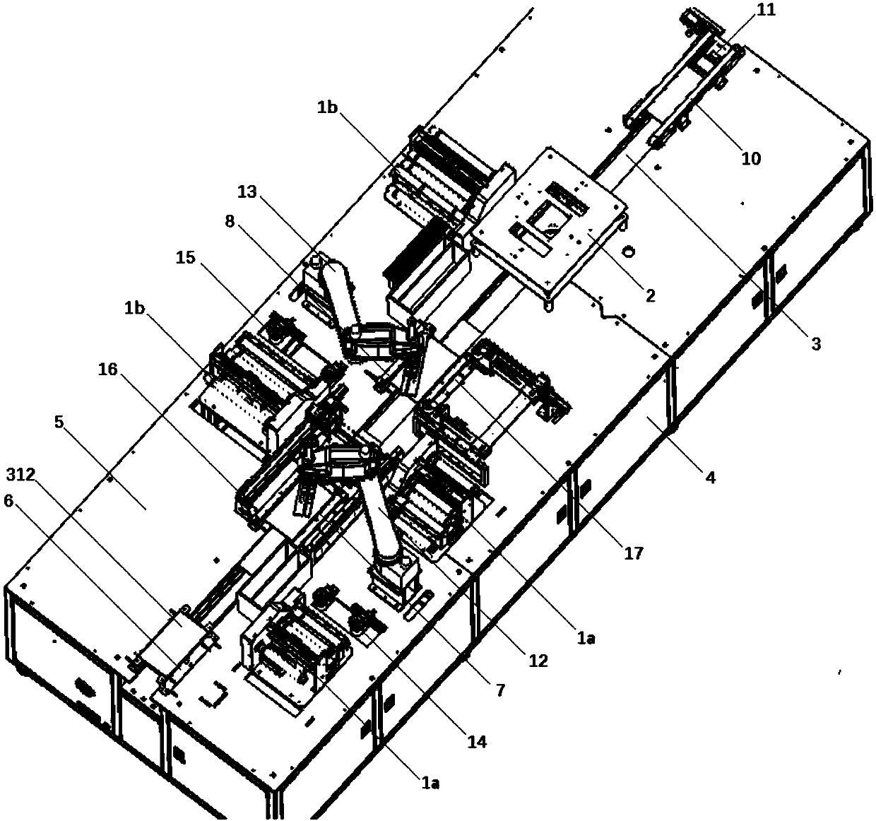
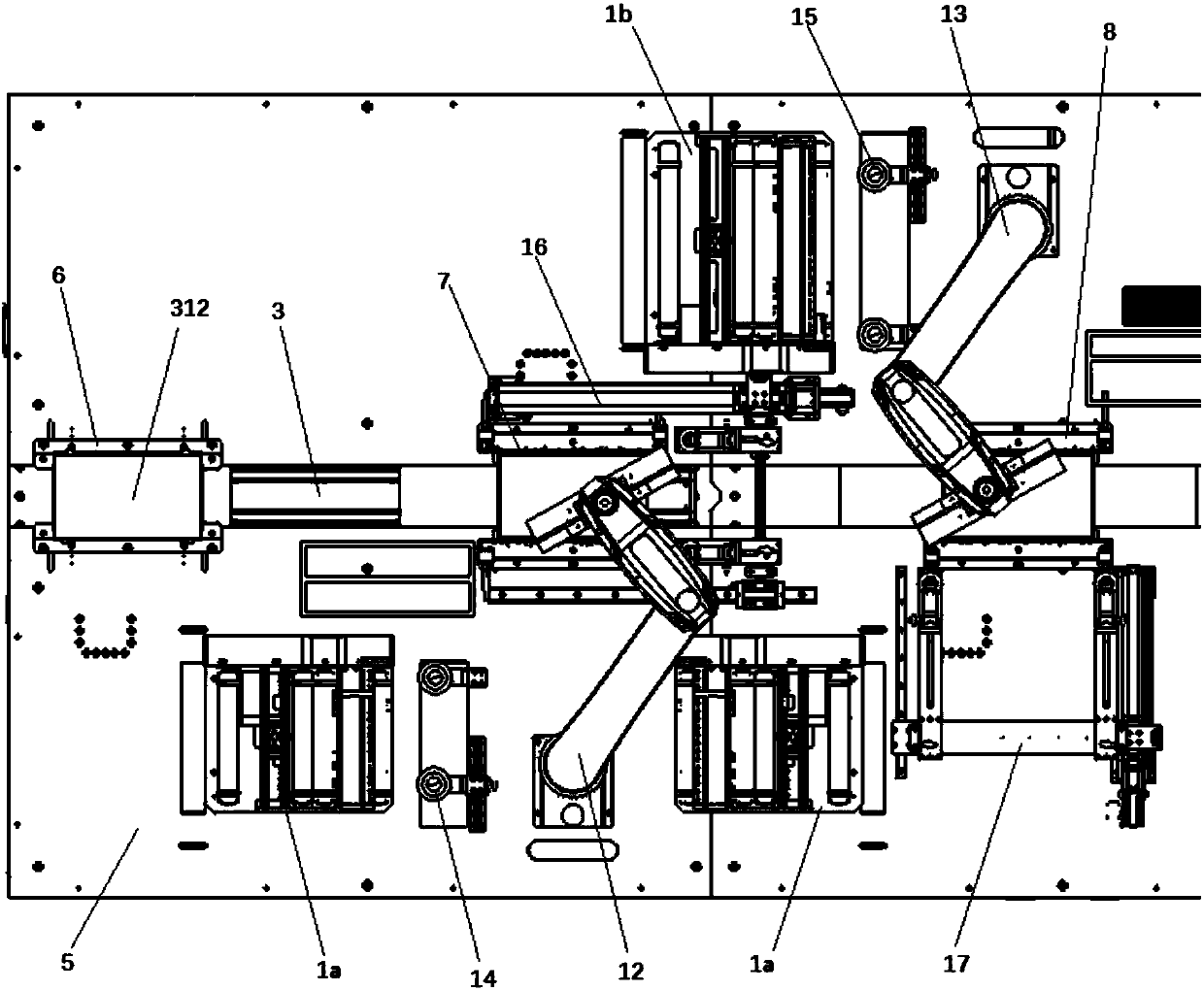
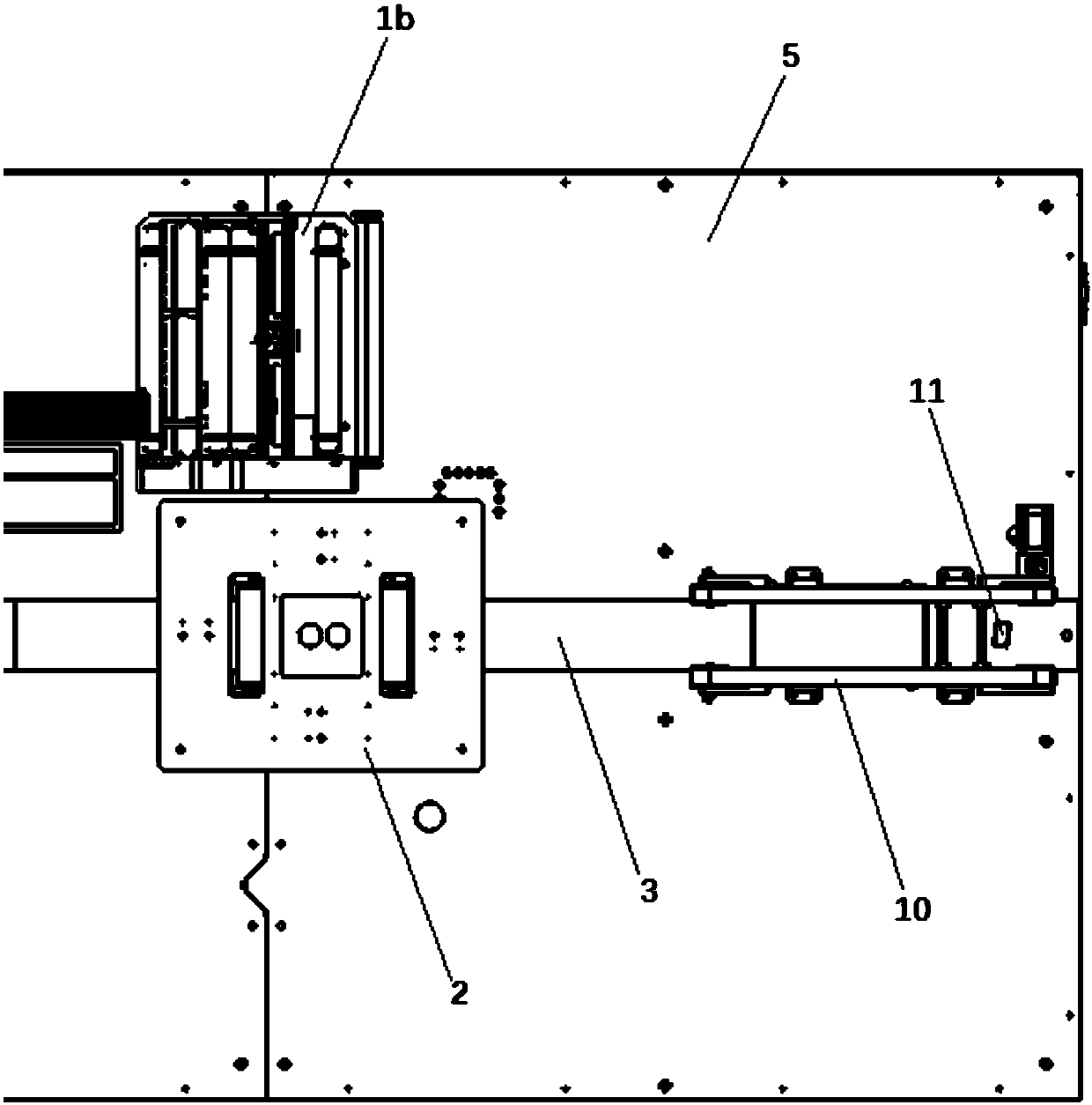
[0054] see Figure 1-5 As shown, an automatic film laminating machine includes an operating table 5 fixed on a frame 4, and the central axis of the operating table 5 is equally divided into 5 stations, which are respectively a product positioning station and a short side material laminating worker. position, long side material filming station, product edge wrapping station and product output station; a transplanting jacking mechanism 3 is buried on the central axis of the operation table 5, and the transplanting jacking mechanism 3 is formed by transplanting The device is composed of 5 jacking devices 307 arranged on the transplanting device. When the transplanting device is in the initial position, the 5 jacking devices 307 are divided into 5 stations, and The five jacking devices 307 are all higher than the operating table 5;

[...


PUM


Abstract

The invention discloses an automatic laminator which comprises a transplant jacking mechanism, a product positioning frame, a first discharging component, a second discharging component, a third discharging component, an edge covering and laminating mechanism, a conveying mechanism, a barcode scanning gun, a short-edge material laminating mechanical-arm component, a long-edge material laminating mechanical-arm component, a short-edge material peeling mechanism, a long-edge material peeling mechanism, a short-edge material detecting device, a long-edge material detecting device, a product short-edge camera positioning component, a product long-edge camera positioning component, etc., which are arranged on an operation table. Through the mutual coordination and match of the transplant jacking mechanism, the material peeling mechanisms, the laminating mechanical-arm components, the edge covering and laminating mechanism, the conveying mechanism, etc., the automatic laminator completes theprocess of feeding, positioning, material peeling, laminating, edge covering, discharging, etc. in order. The automatic laminator realizes the automatic laminating operation of products, reduces thelabor intensity of workers, shortens the laminating time, greatly improves the laminating precision and the laminating efficiency, and reduces the production cost.

Description

technical field [0001] The invention belongs to the field of automation equipment, and in particular relates to an automatic film laminating machine which can replace manual stripping, film laminating and edge wrapping. Background technique [0002] Most of the products need to be filmed on their packaging before leaving the factory. The process mainly includes product transportation, product positioning, film stripping, product filming and product edge wrapping. Some of the processes still use the most primitive of manual operation. [0003] For example, the film must be stripped before the film is attached to the product, but the method of manual stripping not only increases the labor intensity of the workers, but also takes a long time for manual stripping, resulting in relatively low stripping efficiency and increased production costs. When sticking film on products, the manual sticking method not only takes a long time and is labor-intensive, but also has a relatively ...

Claims


Application Information

Patent Timeline
Patent Type & Authority Applications(China)
IPC IPC(8): B65B33/02
CPCB65B33/02Y02P70/50
Inventor 张伟城肖可
Owner 苏州才哲智能科技有限公司
Why Eureka
Try Eureka