
Sludge incinerator structure

A sludge incineration and sludge technology, which is applied in incinerators, combustion methods, combustion types, etc., can solve the problems of unsatisfactory cooling effect and high cost, and reduce the generation of NOx harmful substances, with low cost and good cooling effect. Effect

Pending Publication Date: 2018-03-13
WUXI HUAGUANG BOILER
View PDF4 Cites 3 Cited by
  • Summary
  • Abstract
  • Description
  • Claims
  • Application Information

AI Technical Summary

Problems solved by technology

[0006] Aiming at the above problems of unsatisfactory cooling effect and high cost, the present invention provides a sludge incinerator structure with simple structure, low cost, good cooling effect and guaranteed combustion effect

Method used


Image

  • Sludge incinerator structure
  • Sludge incinerator structure
  • Sludge incinerator structure

Examples


Embodiment Construction

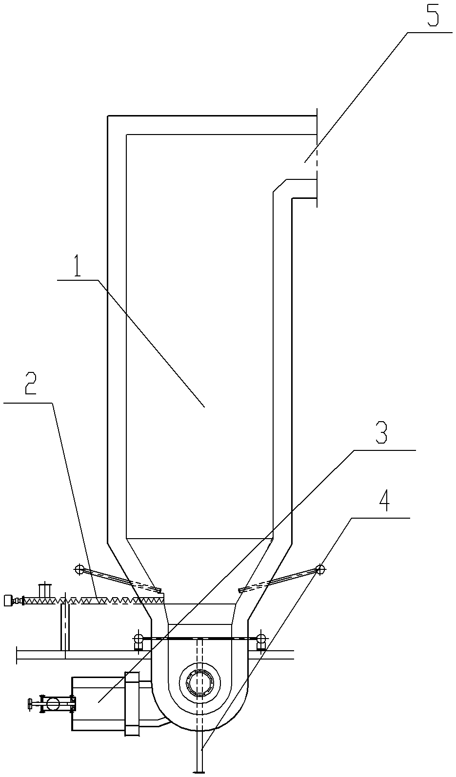
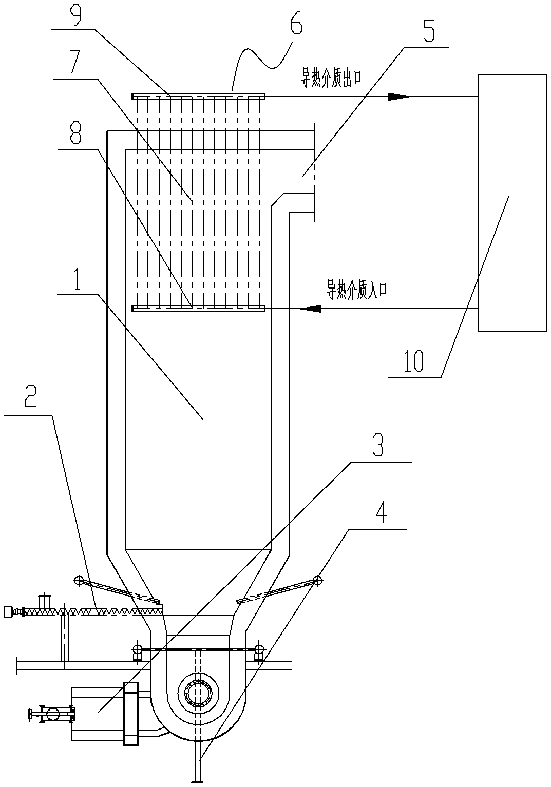
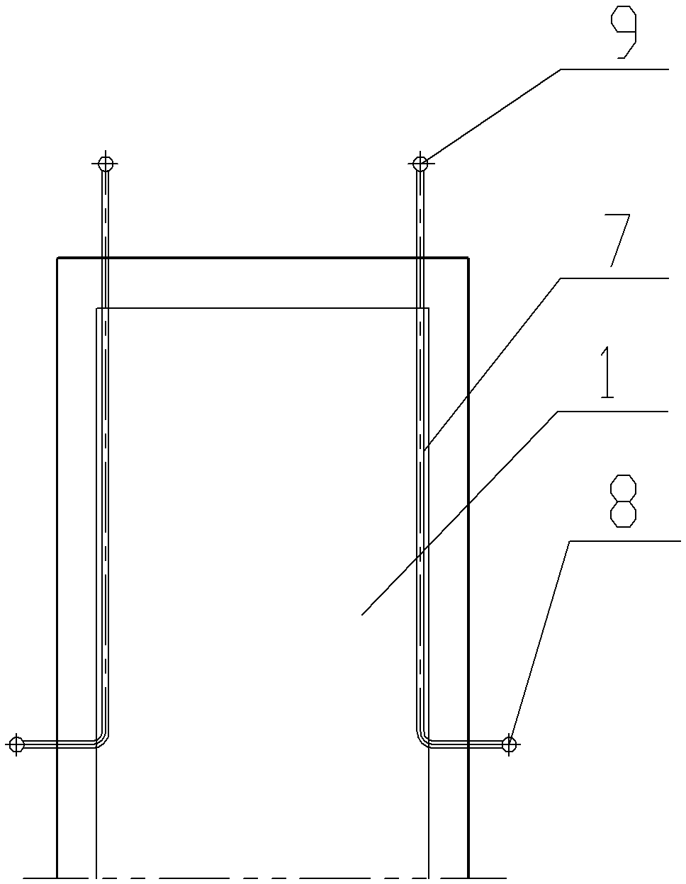
[0014] See figure 2 , image 3 As shown, a sludge incinerator structure, which includes a heat insulating furnace 1, the lower end of the heat insulating furnace 1 is connected to a sludge feeding mechanism 2, an ignition device 3 under the bed and a slag discharge pipe 4, and the sludge feeding mechanism 2 generally adopts a screw feeding mechanism. The upper side of the adiabatic furnace 1 is a high-temperature flue gas outlet 5, and the heat-conducting device 6 is arranged in the adiabatic furnace 1 at the high-temperature flue gas outlet 5. The heat-conducting device 6 includes a heat-conducting tube 7, and one end of the heat-conducting tube 7 runs through the side wall of the adiabatic furnace 1 to connect The heat conduction medium liquid inlet pipe 8, the other end of the heat conduction pipe 7 runs through the top of the adiabatic furnace 1 and is connected to the heat conduction medium liquid outlet pipe 9. Two rows of heat-conducting tubes 7 are arranged in the ad...


PUM


Abstract

The invention relates to the technical field of sludge incineration, in particular to a sludge incinerator structure, which is simple in structure, low in cost and excellent in cooling effect, and guarantees the combustion effect. The sludge incinerator structure comprises a thermal insulation hearth; the lower end of the thermal insulation hearth is connected with a sludge feeding mechanism, an under-bed ignition device and a slag discharge pipe; and the side surface of the upper end of the thermal insulation hearth is provided with a high-temperature flue gas outlet. The sludge incinerator structure is characterized in that a heat conducting device is arranged in the part, at the high-temperature flue gas outlet, of the thermal insulation hearth; the heat conducting device comprises heatconducting pipes; one end of each heat conducting pipe penetrates through the side wall of the thermal insulation heath and is connected with a heat conducting medium inlet pipe; and the other end ofeach heat conducting pipe penetrates through the top of the thermal insulation hearth is connected with a heat conducting medium outlet pipe.

Description

technical field [0001] The invention relates to the technical field of sludge incineration, in particular to a sludge incinerator structure. Background technique [0002] With the improvement of people's living standards, a large number of sewage treatment plants began to be constructed and put into operation one after another. The phenomenon of "heavy sewage treatment and light sludge disposal" is common in my country's sewage treatment industry, which makes it difficult to dispose of a large amount of sludge and seriously affects the quality of the environment, which is highly concerned and valued by the society. [0003] Most of the final disposal methods of sludge from urban sewage treatment plants are sent to landfills for landfill, and some are piled up in the open space around them. This simple disposal method is not suitable for the needs of urban development. The incineration treatment treats the sludge as a kind of solid waste, and performs harmless, resourceful a...

Claims


Application Information

Patent Timeline
Patent Type & Authority Applications(China)
IPC IPC(8): F23G7/00F23G5/50F23G5/46
CPCF23G5/46F23G5/50F23G7/001F23G2206/20F23G2209/12
Inventor 顾虎雄毛军华陆晓焰景磊
Owner WUXI HUAGUANG BOILER
Learn More