Low-nitrogen burner boiler

A low-nitrogen burner and burner technology, applied in the field of combustion boilers, can solve problems such as low burner efficiency, achieve the effects of improving boiler efficiency, broad application prospects, and preventing coking

Inactive Publication Date: 2018-09-21
CHANGZHOU SIYU ENVIRONMENTAL PROTECTION MATERIAL SCI & TECH
View PDF0 Cites 1 Cited by
  • Summary
  • Abstract
  • Description
  • Claims
  • Application Information

AI Technical Summary

Problems solved by technology

[0006] The technical problem to be solved by the present invention is to provide a low-nitrogen burner boiler for the problems that the existing burner discharges carbon oxides and nitrogen oxides exceeding the standard and the burner efficiency is low.

Method used


Image

  • Low-nitrogen burner boiler
  • Low-nitrogen burner boiler

Examples


Embodiment Construction

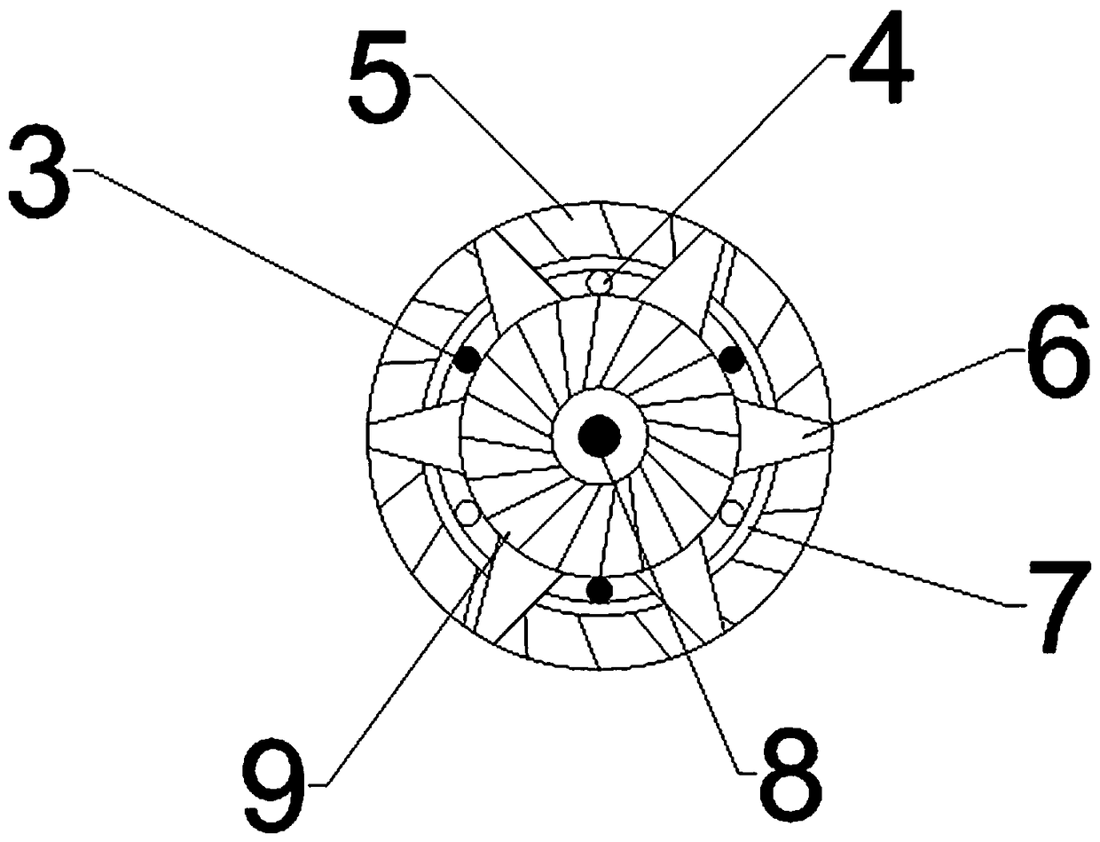
[0022] The pulverized coal is sprayed out through the pulverized coal spray gun 3 and the central pulverized coal spray gun 8 at an exit velocity of 10~20m / s, and the high axial velocity airflow generated by the primary swirling wind wheel 9 ensures that it can penetrate the furnace The air flow improves the mixing of the central air and the central coal, and then the secondary air turbine 5 swirls into the furnace at the periphery to ensure that the air and the unburned particles in the combustion products are fully mixed, forming a package outside the flow pattern of the central swirling air The swirl wind provides excess air for the coal combustion in the periphery, and improves the combustion time of the air and the coal through the swirl flow. The use of the swirl wind at the outermost side helps to form the high-temperature flue gas backflow inside the furnace at the root of the flame, and the well-organized At the same time as the aerodynamic field, it can be ignited in ...


PUM


Abstract

The invention relates to a low-nitrogen burner boiler, and belongs to the technical field of combustion boilers. According to the low-nitrogen burner boiler, pulverized coal is sprayed out through a pulverized coal spray gun and a central pulverized coal spray gun, and a higher axial speed airflow is generated, so that mixing of central air and central coal is improved; a secondary air turbine swirls into a hearth at the periphery to ensure that air and unburned particles in combustion products are fully mixed; wrapped swirling air is formed outside a flow pattern of central swirling air, so that excessive air is provided for the peripheral coal, and the combustion time of the air and the coal is increased through swirling; the swirling air at the outermost side is adopted to help to formhigh-temperature flue gas backflow inside the hearth at the root of flame; at the same time, a well aerodynamic field is organized, timely ignition and full burnout are carried out as well as prevention of producing of coking is carried out, and NOx emission is minimized. The low-nitrogen burner boiler ensures the safe operation of a machine set, the economic efficiency of the machine set is improved, and wide application prospects in the aspects of energy conservation, emission reduction, boiler efficiency improvement and the like are achieved.

Description

technical field [0001] The invention relates to a low-nitrogen burner boiler, which belongs to the technical field of combustion boilers. Background technique [0002] In my country, the power industry is one of the industries with the largest energy consumption and the most serious pollution emissions. Coal occupies a dominant position in my country's energy structure. In 2010, as much as 70% of the total installed capacity of power generation in my country's power industry came from thermal power generating units. The continuous growth of thermal power generation enterprises has gradually revealed their crisis of air pollution, especially the emission of carbon oxides and nitrogen oxides. [0003] The heating furnace is a common device in the production equipment of refining and chemical enterprises, and the NO produced by its combustion x It is a common air pollutant. At present, when no special measures are taken for heating furnaces in refining and chemical enterprises...

Claims


Application Information

Patent Timeline
Patent Type & Authority Applications(China)
IPC IPC(8): F23C9/06
CPCF23C9/003F23C9/06
Inventor 黄名名王文新史玉玲
Owner CHANGZHOU SIYU ENVIRONMENTAL PROTECTION MATERIAL SCI & TECH
Why Eureka
Try Eureka