Integrated electric heating ceramic tile

A ceramic tile and electric heating technology, which is applied in the field of ceramic tiles, can solve problems such as ceramic tile sinking under heavy pressure, carbon crystal leakage, and electric heating plate power increase, etc., to achieve the effect of convenient splicing and installation, and increasing indoor temperature

Pending Publication Date: 2018-03-13
NINGBO JUHUANG AIR CONDITIONING TECH
View PDF15 Cites 2 Cited by
  • Summary
  • Abstract
  • Description
  • Claims
  • Application Information

AI Technical Summary

Problems solved by technology

The tiles made by the above process have the following disadvantages: 1. The glue is easy to leak, resulting in a rough appearance on the back; 2. Since the polyurethane board is a soft material, it will deform under heavy pressure, so that the tiles have the risk of sinking under heavy pressure ; 3. Since the polyurethane plate at the bottom is deformed by force, the heat preservation effect will be reduced, thereby increasing the heat loss of the electric heating tile; 4. The edge of the tile lacks a rigid isolation layer. Once the seal is not good, water can easily enter the carbon crystal electric heating plate in the tile , leading to tile leakage; 5. Due to the large amount of glue used when fixing the electric heating pla

Method used


Image

  • Integrated electric heating ceramic tile
  • Integrated electric heating ceramic tile
  • Integrated electric heating ceramic tile

Examples


Embodiment Construction

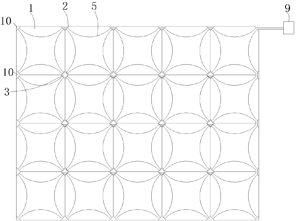
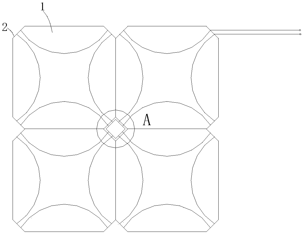
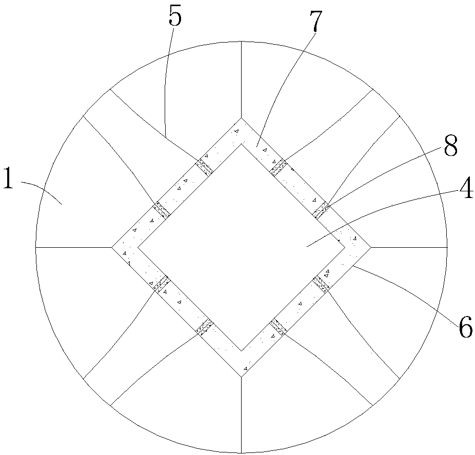
[0020] Such as figure 1 , figure 2 , image 3 As shown, an integrated electric heating tile includes a tile body unit 1 and an electric heating wire group. The four corners of the tile body unit 1 are provided with chamfers, the chamfers are the cutting surfaces 2, and the four corners of the tile body units 1 are spliced. A sealed waterproof junction box 3 is provided, and a transfer terminal (or waterproof plug-in) 4 is provided in the sealed waterproof junction box 3. The heating wire group in the tile body unit 1 is connected to the transfer terminal 4 in the sealed waterproof junction box 3.

[0021] The heating wire group includes a plurality of heating wires arranged in the tile body unit 1 , and the two free ends of the heating wires 5 pass through two adjacent cutting surfaces 2 on the tile body unit 1 .

[0022] An insulating shell 6 is arranged on the outer side of the transfer terminal 4 of the sealed waterproof junction box 3. The insulating shell 6 is square. ...


PUM


Abstract

The invention relates to an integrated electric heating ceramic tile. The integrated electric heating ceramic tile comprises ceramic tile body units and electric heating wire groups. Chamfers are arranged on the four corners of each ceramic tile unit. Cut surfaces are located at the chamfers. The four corner splicing portions of every four ceramic tile body units are provided with a sealed waterproof junction box. A transit binding post (or a waterproof plug-in piece) is arranged in each sealed waterproof junction box. The electric heating wire groups in the ceramic tile body units are connected with the transit binding posts in the sealed waterproof junction boxes (or the electric heating wires and the waterproof plug-in pieces are in butt joint in box bodies in an integrated compoundingmanner). The electric heating wires are connected with the transit binding posts (or the waterproof plug-in pieces) through threaded columns or male tabs. When the ceramic tile body units are spliced,the apex angles of every four ceramic tile body units correspond to one sealed waterproof junction box, and then one large heating floor tile unit can be composed, and the sealed waterproof junctionbox has the functions of transit and electric conduction. The integrated electric heating ceramic tile has the main advantages that spicing and installation are convenient, the installation environment is flexible, the heat conversion efficiency is high, and the number of the ceramic tile body units can be changed at will according to the size of a site.

Description

technical field [0001] The invention relates to the field of tiles, in particular to an integrated electric heating tile. Background technique [0002] The existing electric heating tile technology is to use glue on the back of the traditional ceramic tile to stick the carbon crystal electric heating plate to the back, and then glue the polyurethane plate on the back of the electric heating plate. The tiles made by the above process have the following disadvantages: 1. The glue is easy to leak, resulting in a rough appearance on the back; 2. Since the polyurethane board is a soft material, it will deform under heavy pressure, so that the tiles have the risk of sinking under heavy pressure ; 3. Since the polyurethane plate at the bottom is deformed by force, the heat preservation effect will be reduced, thereby increasing the heat loss of the electric heating tile; 4. The edge of the tile lacks a rigid isolation layer. Once the seal is not good, water can easily enter the car...

Claims


Application Information

Patent Timeline
IPC IPC(8): F24D13/02E04F15/08
CPCF24D13/024E04F15/082E04F2290/023
Inventor 刘金生
Owner NINGBO JUHUANG AIR CONDITIONING TECH
Why Eureka
Try Eureka