Brushless motor test device and test method

A technology of brushless motor and test method, applied in the direction of motor generator test, measuring device, measuring electricity, etc., can solve the problems of low test efficiency and low accuracy, and achieve the effect of high test efficiency, fast speed and reasonable design

Inactive Publication Date: 2018-03-13
上海锦科电气科技有限公司
View PDF4 Cites 1 Cited by
  • Summary
  • Abstract
  • Description
  • Claims
  • Application Information

AI Technical Summary

Problems solved by technology

Existing testing methods have the disadvantages of low accuracy and low testing efficiency

Method used


Image

  • Brushless motor test device and test method
  • Brushless motor test device and test method

Examples


Embodiment Construction

[0020] The technical solution of this patent will be further described in detail below in conjunction with specific embodiments.

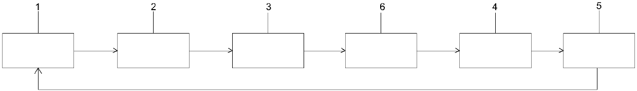
[0021] see Figure 1-2 , a brushless motor testing device, including a servo motor controller 1, a servo motor 2, a shaft coupling 3, a signal processing circuit system 4 and a signal acquisition and analysis software system 5; one end of the servo motor 2 is connected to the servo motor controller 1. The other end of the servo motor controller 1 is connected to the signal acquisition and analysis software system 5. The servo motor controller 1 is used to control the operation of the servo motor 2. The output shaft of the servo motor 2 is connected to the motor under test 6 through a coupling 3, The Hall sensor signal line and the winding lead-out line of the motor under test 6 are connected to the signal input end of the signal processing circuit system 4, and the signal processing circuit system 4 obtains the Hall sensor signal of the motor under...


PUM


Abstract

The invention discloses a brushless motor test device and test method. The brushless motor test device includes a servo motor controller, a servo motor, a coupling, a signal processing circuit system,and a signal acquisition and analysis software system. One end of the servo motor is connected to the servo motor controller, and the other end of the servo motor controller is connected to the signal acquisition and analysis software system. The servo motor controller is used for controlling the operation of the servo motor. The output shaft of the servo motor is connected to a measured motor through the coupling. The Hall sensor signal line and the winding lead-out line of the measured motor are connected to the signal input end of the signal processing circuit system. The signal output endof the signal processing circuit system is connected to the signal acquisition and analysis software system. The brushless motor test device and test method have the advantages of high test accuracy,high test efficiency, convenience of use, high speed, simple test method and good repeatability, and can be better applied to full inspection on a production line.

Description

technical field [0001] The invention relates to the field of automatic testing and measurement, in particular to a brushless motor testing device and testing method. Background technique [0002] In brushless motor control applications, it is of great significance to obtain the position information of the brushless motor rotor. At present, two methods are usually used to obtain the position information of the brushless motor rotor. One is to install a Hall sensor corresponding to the number of motor stator windings inside the motor, and the other is to use the back EMF signal generated on the stator winding when the motor rotor rotates. In the process of motor production, due to the guarantee of the production process, such as the change of the installation angle and distance of the Hall sensor, the change of the magnetization intensity of the motor rotor, and the parameter difference of the Hall sensor itself, etc., the obtained brushless motor often The position informati...

Claims


Application Information

Patent Timeline
Patent Type & Authority Applications(China)
IPC IPC(8): G01R31/34
CPCG01R31/343G01R31/346
Inventor 王珏
Owner 上海锦科电气科技有限公司
Why Eureka
Try Eureka