Method and system for realizing inspection of steel strip punching by machine vision

A machine vision and punching technology, applied in the field of inspection, can solve the problems such as the inability to obtain the image of the punched steel strip, the indeterminate speed of the punching steel strip, and the inability to sample during the production process. , Improve the effect of detection accuracy

Active Publication Date: 2020-09-11
HUNAN UNIV OF ARTS & SCI
View PDF11 Cites 0 Cited by
  • Summary
  • Abstract
  • Description
  • Claims
  • Application Information

AI Technical Summary

Problems solved by technology

The manual detection has the following defects: ①The detection efficiency is low and it is easy to miss; ②Because the punched steel strip is coiled and produced continuously, sampling cannot be carried out during the production process, so even if there is a production problem, the problem cannot be found in time, so manual The detection is difficult to match with the current punching steel strip processing and manufacturing process
With the continuous winding of the punched steel strip, the winding radius gradually increases, which leads to the uncertainty of the forward speed of the punched steel strip on the punching production line, which brings great challenges to the inspection of the steel strip punching process.
[0006] The second is that the detection process must meet the detection accuracy requirements of 0.01mm! Assuming that one pixel on the image of the upper surface of the punched steel strip corresponds to a size of 0.005mm, the image corresponding to the width of the punched steel strip needs to have at least 400mm / 0.005mm=80000 pixels, and the punched hole The width of the steel strip may actually exceed 400mm. Obviously, it is impossible to obtain a complete image of the upper surface of the punched steel strip through a camera at a fixed position.

Method used


Image

  • Method and system for realizing inspection of steel strip punching by machine vision
  • Method and system for realizing inspection of steel strip punching by machine vision
  • Method and system for realizing inspection of steel strip punching by machine vision

Examples


Embodiment Construction

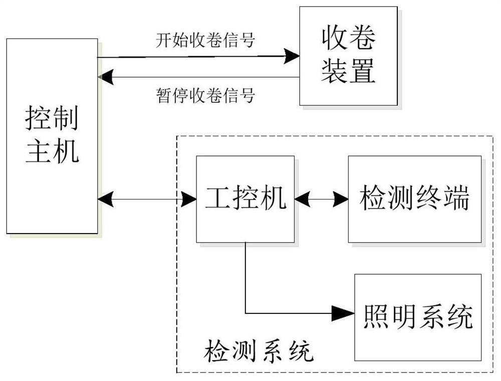
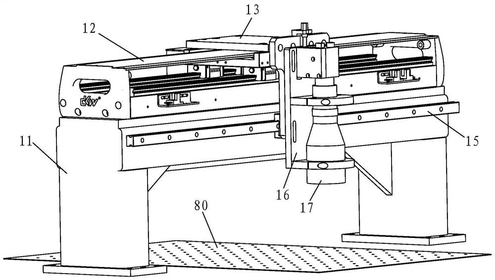
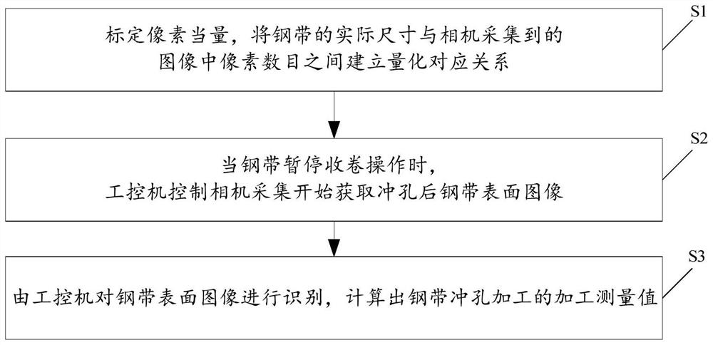
[0032] For this reason, the present invention proposes a kind of method and system that adopts machine vision to realize steel strip punching processing detection, by means of moving machine vision, the images of the upper surface of the punched steel strip after punching are sampled in stages, and the upper surface of the steel strip is analyzed. The image is processed and analyzed to obtain the detection result.

[0033] The steel strip punching processing detection system proposed by the present invention mainly includes an industrial computer, at least one detection terminal based on motion machine vision and a lighting system located below the punched steel strip. The detection terminal and the lighting system are both Connected with the industrial computer, the lighting system provides a light source with stable brightness and no flickering so that the detection terminal can collect the image of the upper surface of the punched steel strip.

[0034] The winding device is...


PUM


Abstract

The present invention discloses a method and system of adopting the machine vision to realize the steel belt punching processing detection, wherein the method comprises the steps of pre-determining apixel equivalent gamma and a compensation value; controlling a linear motor to drive a camera to start moving rightwards along a linear guide rail and from a working origin O arranged at the left sideof a steel belt, and using the camera to search and determine the left edge of the punched steel belt; controlling the linear motor to drive the camera to move continuously and rightwards from the left edge of the steel belt, obtaining a plurality of steel belt upper surface images during the movement process of the camera, separately identifying the punching on each steel belt upper surface image, and calculating the detection results; using the camera to search and determine the right edge of the punched steel belt, calculating the total width of the steel belt and controlling the linear motor to drive the camera to return to the working origin O. The method and the system of the present invention utilize the camera to realize the processing detection of the wide punched steel belt of larger size, are accurate in detection results, and accord with the high-precision detection requirement.

Description

technical field [0001] The invention relates to detection technology, in particular to a method and system for realizing the detection of steel strip punching processing by using machine vision. Background technique [0002] The punched nickel-plated steel strip is a product obtained by punching holes on the surface of the cold-rolled white steel strip, and then performing electrochemical nickel plating. It has good electronic conductivity and corrosion resistance, high cost performance, suitable for large-scale continuous production, and is widely used as a current collector material for batteries. At present, it is mainly used in the fields of MH-Ni battery, nickel-cadmium battery for tools, sintered battery for military industry and battery plate manufacturing for rail transit. [0003] The punching (punching) process in the process of punching nickel-plated steel strip is a key link in product formation, and key technical indicators such as punching hole diameter, horiz...

Claims


Application Information

Patent Timeline
Patent Type & Authority Patents(China)
IPC IPC(8): G05B19/404G01B11/00
CPCG01B11/002G05B19/404G05B2219/35063G05B2219/37009
Inventor 李建奇曹斌芳肖进春彭朋飞张自轩聂方彦杨峰田中杰
Owner HUNAN UNIV OF ARTS & SCI
Why Eureka
Try Eureka