Control method of electronic equipment charging cabinet

A control method and technology of electronic equipment, applied in the direction of electric vehicle charging technology, battery circuit device, arrangement of multiple synchronous batteries, etc., can solve charging cabinet charging, need people to guard, etc., to achieve automatic operation and intelligent storage Take and realize the effect of centralized management

Inactive Publication Date: 2018-03-13
CHENGDU EXPERT OF BATTERY DESIGN TECH CO LTD
View PDF0 Cites 0 Cited by
  • Summary
  • Abstract
  • Description
  • Claims
  • Application Information

AI Technical Summary

Problems solved by technology

[0004] The purpose of the present invention is to provide a control method for an electronic device charging cabinet to solve the problem of charging mobile phones or other electronic devices when people go out, and solve the problem that people need to be guarded when charging electronic devices. Solve the problem of centralized management of electronic equipment charging, solve the problem of intelligent access to electronic equipment; solve the problem of wireless charging of equipment; solve the problem of charging cabinet charging

Method used


Image

  • Control method of electronic equipment charging cabinet
  • Control method of electronic equipment charging cabinet
  • Control method of electronic equipment charging cabinet

Examples


Embodiment 1

[0039] On the basis of the above embodiments, the present invention discloses a preferred embodiment of an electronic equipment charging cabinet. The pressing mechanism includes a connecting head 17 and an engaging block 21. One end of the connecting head 17 is connected to the pressing plate 12. The other end of the head 17 is provided with an engaging tooth 24; the connecting head 17 has a shaft hole; the engaging block 21 is arranged on the slot 11, and the engaging block 21 is provided with an upper engaging groove 22, a lower engaging groove 23, and an upper engaging groove 22 Separated from the lower engagement groove 23 by smooth protrusions; the engagement tooth 24 can be engaged with the upper engagement groove 22 or the lower engagement groove 23; the pressing mechanism includes a rotating shaft 18, which passes through the rotating shaft hole, and is connected to Dowel 19, dowel 19 links to each other with slot 11 by back-moving spring 20; When cooperating with the ...

Embodiment 2

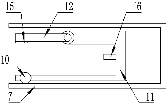
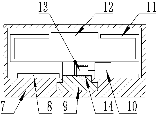
[0042] On the basis of embodiment 1, a chute is provided on the charging tank 7, and the slide rail 9 is matched with the chute, and the slide rail 9 can move in the chute, and the slide rail 9 is provided with a rack 14; 7 is provided with a driving motor 10, the rotating shaft of the driving motor 10 is connected with a gear 13, the gear 13 is meshed with the rack 14, the driving motor 10 can drive the slide rail 9 to move through the gear 13; the pressing plate 12 is provided with a cushion 15. The control circuit includes a central control unit and a motor drive circuit, and the central control unit is electrically connected to the drive motor 10 through the motor drive circuit.

[0043] When the slot 11 pops up, the central control unit controls the drive motor 10 to rotate in the forward direction through the motor drive circuit, and the drive motor 10 drives the gear 13 to rotate, and the gear 13 meshes with the rack 14 to convert the rotation into a linear drive. In th...

Embodiment 3

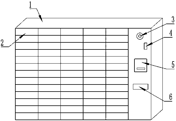
[0045] On the basis of Embodiment 1 or 2, the interface of the charging plug 16 includes a Micro USB interface, a USB Type C interface and a Lightning interface; the charging grid 2 matches the charging slot 7, and the charging grid 2 on the charging cabinet 1 has specifications of Various, can accommodate electronic devices of different sizes and structures for charging.

[0046] The charging circuit can provide electric energy for the electronic equipment, and the central control unit can adjust the charging mode and the charging current according to the type of the electronic equipment and the input equipment, so as to achieve the maximum charging effect and ensure the charging efficiency. Micro USB interface, USB Type C interface and Lightning interface include most of the charging interface ports of electronic devices on the market, greatly improving the scope of services. The charging connector is replaced according to the change of the interface. Customers can basicall...


PUM


Abstract

The invention discloses a control method of an electronic equipment charging cabinet. The charging cabinet comprises a cabinet body, the cabinet body is provided with several charging checks, the charging checks comprise charging slots, the charging slots are internally provided with plugging slots, the plugging slots are provided with pressing plates used for pressing electronic equipment, and the pressing plates are movably connected with the plugging slots through pressing mechanisms; driving mechanisms are arranged at the bottoms of the plugging slots, the plugging slots can linearly movein the charging slots through the driving mechanisms, the driving mechanisms comprise slide rails, and the slide rails are connected with the plugging slots; the charging slots are provided with charging coils, the plugging slots are provided with charging plugs, and the cabinet body is provided with a coin putting device; the electronic equipment charging cabinet comprises a control circuit, andthe driving mechanisms, the charging coils and the charging plugs are in signal connection with the control circuit through a cable. The control method of the electronic equipment charging cabinet canmake it convenient for people to charge on public places where charging is inconvenient, centralized management of mobile phone charging is achieved, and people do not need to wait aside; after charging is completed, the mobile phone can be taken back through identity recognition; automated fee collecting can be conducted; wireless charging of the electronic equipment can be achieved.

Description

technical field [0001] The invention relates to a charging cabinet, in particular to a control method for the charging cabinet of electronic equipment. Background technique [0002] With the popularization of electronic devices, smart phones have become an indispensable part of people's lives, but with more and more functions of smart phones and continuous enhancement of performance, the normal use time of mobile phones is getting shorter and shorter , causing the device to need to be charged frequently, but when people go shopping or playing, they often encounter the problem that the battery of the mobile phone is exhausted and cannot be used, causing great inconvenience. [0003] In the existing technology, a power bank is usually used for emergency charging, but the power bank is bulky, heavy, inconvenient to carry, and needs to be charged, which is very troublesome. Therefore, it is extremely urgent to solve the problem of charging electronic devices outdoors. Content...

Claims


Application Information

Patent Timeline
Patent Type & Authority Applications(China)
IPC IPC(8): G07F15/00G06Q20/18H02J7/00
CPCG06Q20/18G07F15/006H02J7/0013Y02T90/12
Inventor 代炎利刘旭芝邓佳
Owner CHENGDU EXPERT OF BATTERY DESIGN TECH CO LTD
Why Eureka
Try Eureka