Continuous thermal processing device and thermal processing method of MgB2 superconduction wire/strip
A heat treatment device and superconducting wire technology, applied in the field of heat treatment, can solve the problems of long heating and cooling time, affecting the superconductivity of wire/strip, and adhesion of wire/strip, and achieve the effect of improving heat treatment, increasing length and improving quality
- Summary
- Abstract
- Description
- Claims
- Application Information
AI Technical Summary
Problems solved by technology
Method used
Image

Examples
Embodiment 1
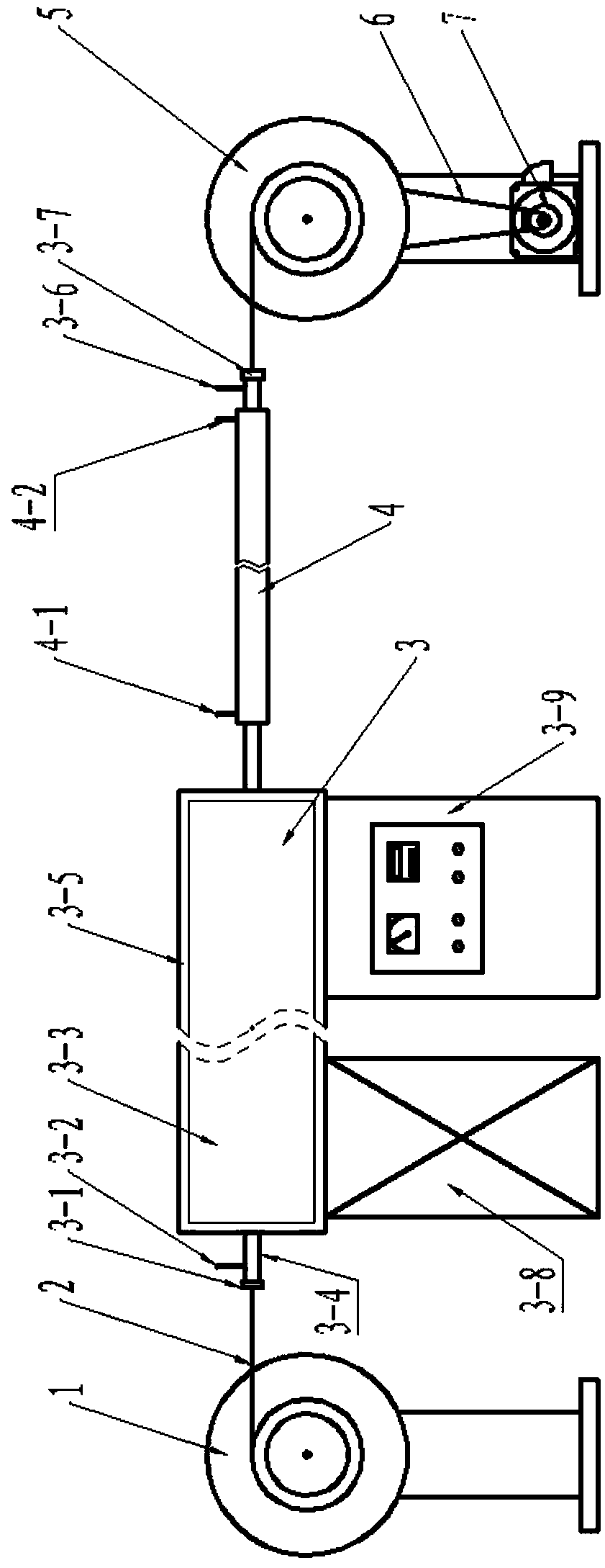
[0032] Such as figure 1The shown continuous heat treatment device includes a heat treatment furnace 3, and the heat treatment furnace 3 includes a furnace body 3-3, a temperature controller 3-9 and a furnace frame 3-8 for supporting the furnace body 3-3. The furnace body 3-3 is pierced with a furnace tube 3-4, and both ends of the furnace tube 3-4 protrude from the furnace body 3-3, and the two ends of the furnace tube 3-4 are respectively equipped with a furnace tube inlet end The cap mouth 3-1 and the furnace pipe outlet end cap mouth 3-7, the furnace pipe 3-4 is equipped with an air inlet 3-2 at one end of the furnace pipe inlet cap mouth 3-1, and the furnace pipe 3-4 An air outlet 3-6 is provided at one end of the cap opening 3-7 of the outlet end of the furnace tube, and a sleeve cooler 4 is set on the furnace tube 3-4 close to the cap opening 3-7 of the outlet end of the furnace tube. The tube cooler 4 is provided with a cooling water inlet 4-1 and a cooling water outle...
Embodiment 2
[0036] This embodiment includes the following steps:
[0037] Step 1. Put the 12-core MgB 2 The starting end of the superconducting strip is connected to one end of the lead wire 2 passing through the cap opening 3-1 of the inlet end of the furnace tube, and then wound on the pay-off wheel 1, and then the other end of the lead wire 2 is passed through the cap opening 3 of the outlet end of the furnace tube -7 is wound on the take-up reel 5; the 12-core MgB 2 The cross-section of the superconducting tape is a rectangle of 0.4mm×3.2mm;
[0038] Step 2. Adjust the temperature in the furnace tube 3-4 to 650°C through the temperature controller 3-9, pass the argon gas into the furnace tube 3-4 through the air inlet 3-2, and push the air from the air outlet 3-6 Discharge, then close the air inlet 3-2 and the exhaust hole 3-6, make the furnace tube 3-4 stable at 650°C for 10 minutes, and then pass the water into the sleeve cooler 4 through the cooling water inlet 4-1 , discharged ...
Embodiment 3
[0047] This embodiment includes the following steps:
[0048] Step 1, the 7-core MgB 2 The starting end of the superconducting wire is connected to one end of the lead wire 2 passing through the cap opening 3-1 of the inlet end of the furnace tube, and then wound on the pay-off wheel 1, and then the other end of the lead wire 2 is passed through the cap opening 3-1 of the outlet end of the furnace tube. 7 is wound on the take-up reel 5; The 7-core MgB 2 The diameter of the superconducting wire is 1.0mm;
[0049] Step 2. Adjust the temperature in the furnace tube 3-4 to 700°C through the temperature controller 3-9, pass the argon gas into the furnace tube 3-4 through the air inlet 3-2, and push the air from the air outlet 3-6 Discharge, then close the air inlet 3-2 and the exhaust hole 3-6, make the furnace tube 3-4 stable at 700°C for 10 minutes, and then pass the water into the sleeve cooler 4 through the cooling water inlet 4-1 , discharged from the cooling water outlet 4...
PUM
| Property | Measurement | Unit |
|---|---|---|
| diameter | aaaaa | aaaaa |
| diameter | aaaaa | aaaaa |
Abstract
Description
Claims
Application Information
 - R&D
- Intellectual Property
- Life Sciences
- Materials
- Tech Scout
- Unparalleled Data Quality
- Higher Quality Content
- 60% Fewer Hallucinations
Browse by: Latest US Patents, China's latest patents, Technical Efficacy Thesaurus, Application Domain, Technology Topic, Popular Technical Reports.
© 2025 PatSnap. All rights reserved.Legal|Privacy policy|Modern Slavery Act Transparency Statement|Sitemap|About US| Contact US: help@patsnap.com