

Operation method of ampoule laser wire drawing filling and sealing machine
An operation method and technology of a filling and sealing machine, which are applied in the directions of liquid materials, packaging, packaging items, etc., can solve the problems of unsafe inflammable and explosive substances, the impact of pharmaceutical environment, a large amount of waste gas, etc., and achieve remarkable use effect and avoid sealing. Effects of poor quality, constant heating temperature
- Summary
- Abstract
- Description
- Claims
- Application Information
AI Technical Summary
Problems solved by technology
Method used
Image

Examples
Embodiment 1
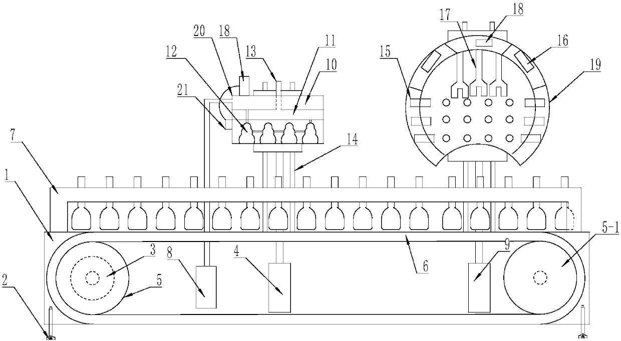
[0017] The box body 1 is a cuboid structure, a cavity is set inside the box body 1, anchor bolts 2 are arranged at the four corners of the bottom surface of the box body 1, driving wheels 5 and driven wheels 5-1 are set at both ends of the box body 1 cavity, and the driving wheels 5-1 The motor 3 is arranged on the side, the motor shaft of the motor 3 is located at the center of the driving wheel 5, the conveyor belt 6 is arranged between the driving wheel 5 and the outer periphery of the driven wheel 5-1, and the top surface of the box body 1 is provided with a rectangular hole corresponding to the conveyor belt 6, and the box body 1 Both ends of the rectangular hole on the top surface are equipped with an inverted U-shaped positioning frame 7, and the vacuum machine 8, the No. 1 cylinder 4, the No. 2 cylinder 9, the piston rod of the No. 1 cylinder 4 and the No. A sliding mechanism is arranged above the piston rod of the cylinder 9. The structure of the sliding mechanism is: ...
Embodiment 2
[0022]An operation method of an ampoule laser wire drawing filling and sealing machine. The box body 1 adjusts its own height and levelness through the anchor bolts 2 at the four corners of the bottom surface, and the medicine bottle is placed in the rectangular hole on the top surface of the box body 1. The upper part of the medicine bottle is The side is in contact with the inverted U-shaped positioning frame 7, and the inverted U-shaped positioning frame 7 ensures the centered position of the medicine bottle. After the motor 3 is started, the motor shaft of the motor 3 drives the driving wheel 5 to rotate, and the driving wheel 5 drives the conveyor belt 6 to run, and the conveyor belt 6 drives The driven wheel 5-1 rotates, and the conveyor belt 6 drives the medicine bottle to move forward to the bottom of the medicine filling mechanism 20. When the sensor 21 of the medicine filling mechanism 20 senses the medicine bottle, the sensor 21 transmits the sensing signal to the med...
Embodiment 3
[0024] The outer surface of the conveyor belt 6 is provided with a groove corresponding to the bottom of the medicine bottle.
PUM
 Abstract
Description
Claims
Application Information