
Generator stator hoisting steering system and method thereof

A generator stator and steering system technology, applied to cranes, transportation and packaging, load hanging components, etc., can solve problems such as long preparation period, difficulty in meeting hoisting and steering requirements, and reduced clearance of lifting height, etc., to achieve Save the cost of mechanical shifts, solve the problem of stator steering, and reduce the weight of the load

Inactive Publication Date: 2018-03-16
JIANGXI THERMAL POWER CONSTR CORP
View PDF0 Cites 2 Cited by
  • Summary
  • Abstract
  • Description
  • Claims
  • Application Information

AI Technical Summary

Problems solved by technology

Traditionally, there are two methods for the hoisting and steering of the generator stator. One is to use Rausinger or double-bridge double-girder cranes for hoisting, rotate 90° in the ground maintenance passage, and then install it in place, but Rausinger hoisting costs It is relatively large, and the preparation period is long, and a 250t steering hook must be equipped under the hoisting pole. In addition to the height of other special slings and the length of the hoisting wire rope, the headroom of the hoisting height is reduced. Generally, it is difficult to meet the requirements of hoisting and turn to demand
Secondly, the conventional bridge-type double-girder crane hoisting method has more hoisting equipment attached to the bridge-type double-girder crane, and the weight is relatively large. The two bridge-type double-girder cranes in the machine room cannot meet the lifting requirements.
Another method is ground steering. Firstly, the generator stator is unloaded to the ground, and then the generator stator is rotated 90° by using a turntable or a steel rail with a hydraulic thruster. However, this method is time-consuming, laborious, and has great limitations and requires professional tools. and team

Method used


Image

  • Generator stator hoisting steering system and method thereof
  • Generator stator hoisting steering system and method thereof
  • Generator stator hoisting steering system and method thereof

Examples


Embodiment Construction

[0022] In order to make the purpose, technical solution and advantages of the present invention clearer, the present invention will be described in detail below in conjunction with the accompanying drawings.

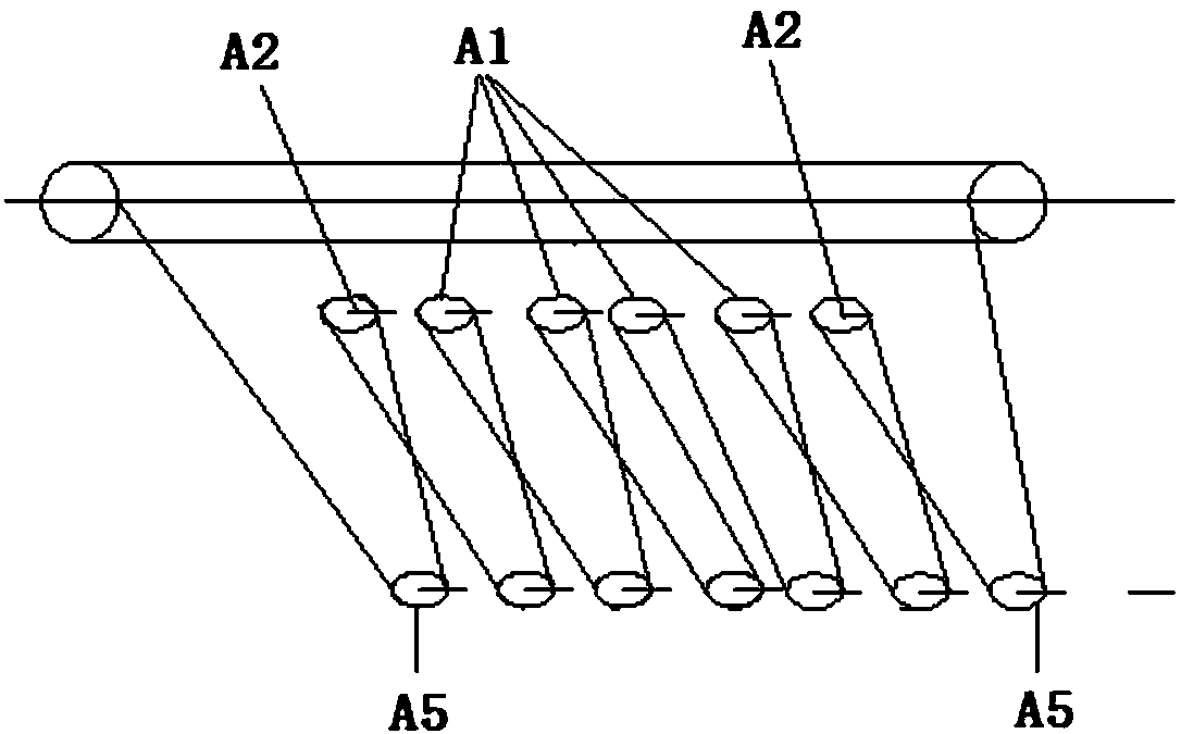
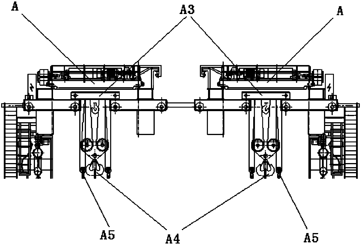
[0023] A generator stator hoisting and steering system, including two bridge-type double-girder cranes A with flexible connection, a special self-made hoisting shoulder beam B, fixed pulley assembly, movable pulley assembly, wire rope assembly and a set of lifting and steering auxiliary equipment, The fixed pulley assembly includes the original fixed pulley A1 next to the main hoisting mechanism (main winch) of each bridge type double-girder crane and 2 additional fixed pulleys A2 respectively increased on both sides thereof, and the movable pulley assembly includes the original fixed pulley A1 There are movable pulleys and 2 additional movable pulleys A5 beside the main hook A4 connected under the trolley A3 of each bridge-type double-girder crane; the wire rope componen...


PUM


Abstract

The invention discloses a generator stator hoisting and steering system and a method thereof. The generator stator hoisting and steering system includes two bridge-type double-girder cranes (A) that are flexibly connected, and a special-purpose self-made hoisting pole beam (B). , a fixed pulley assembly, a movable pulley assembly, a steel wire rope assembly and a set of lifting and steering auxiliary equipment, the fixed pulley assembly includes the original fixed pulley (A1) next to the main hoisting mechanism of each bridge-type double-girder crane and its two sides 2 additional fixed pulleys (A2) are added each, and the movable pulley assembly includes the original movable pulley and 2 additional movable pulleys ( A5); the steel wire rope assembly includes re-threaded main hoisting mechanism steel wire ropes and newly added hoisting steel wire ropes, and the magnification of the main hoisting mechanism steel wire ropes is refitted from the original "five-five to ten" to "seven to seven to fourteen" "magnification, reduce the traction force of the head end of the main hoisting mechanism.

Description

technical field [0001] The invention belongs to the field of large-scale equipment hoisting in the electric power construction industry, and relates to a generator stator hoisting steering system and a method thereof. Background technique [0002] In the electric power construction project, the generator stator is one of the large-scale equipment in the project. The labor intensity of the hoisting project is high, the workload of installation and dismantling is heavy, and the dependence on professional tools is getting stronger and stronger. [0003] The generator stator generally needs to be arranged vertically on the platform of the operation floor of the turbine room, and the generator stator is generally transported horizontally to the maintenance channel by a transport trolley, and then the generator stator is unloaded, rotated 90°, and hoisted in place using special tools. Traditionally, there are two methods for the hoisting and steering of the generator stator. One i...

Claims


Application Information

Patent Timeline
Patent Type & Authority Applications(China)
IPC IPC(8): B66C1/12B66C13/08B66C17/00
CPCB66C1/12B66C13/08B66C17/00
Inventor 尹伟金李红林罗国根闵子浔
Owner JIANGXI THERMAL POWER CONSTR CORP
Learn More