Automatic dredging device for waste incineration power plant leachate grating plates

A technology of waste incineration and grid plate, which is applied in the direction of contaminated groundwater/leachate treatment, special treatment targets, water/sewage treatment, etc., and can solve problems such as increasing incineration costs, diffusion of odorous gases, and reducing the calorific value of waste. Achieve the effects of improving operational efficiency and safety, improving dredging efficiency, and improving operational efficiency

Pending Publication Date: 2018-03-16
徐州中矿长安科技有限公司
View PDF0 Cites 5 Cited by
  • Summary
  • Abstract
  • Description
  • Claims
  • Application Information

AI Technical Summary

Problems solved by technology

[0005] 1. The concentration of leachate is high, viscous, and the flow speed is slow, and the slag and plastic falling to the bottom of the garbage pool will also affect the directional flow of leachate, and even block the leachate grid plate, resulting in leachate The liquid cannot be drained in time
[0006] 2. A large amount of leachate accumulates at the bottom of the pool, which may cause the phenomenon of "leachate soaking garbage"
This will reduce the calorific value of the garbage, so that the incineration process requires more combustion aids, thereby increasing the cost of incineration
[0007] 3. If the leachate cannot be discharged in time, it will cause the spread of malodorous gas and pollute the environment
[0008] 4. Due to the poor drainage of garbage leachate, the actual volumetric den

Method used


Image

  • Automatic dredging device for waste incineration power plant leachate grating plates
  • Automatic dredging device for waste incineration power plant leachate grating plates
  • Automatic dredging device for waste incineration power plant leachate grating plates

Examples


Embodiment Construction

[0025] The present invention will be further described below in conjunction with the accompanying drawings.

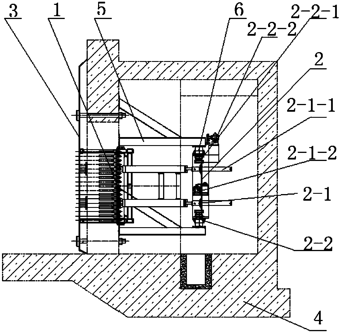
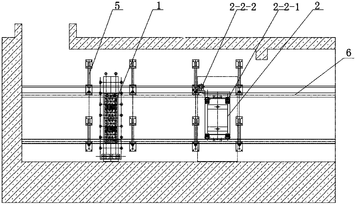
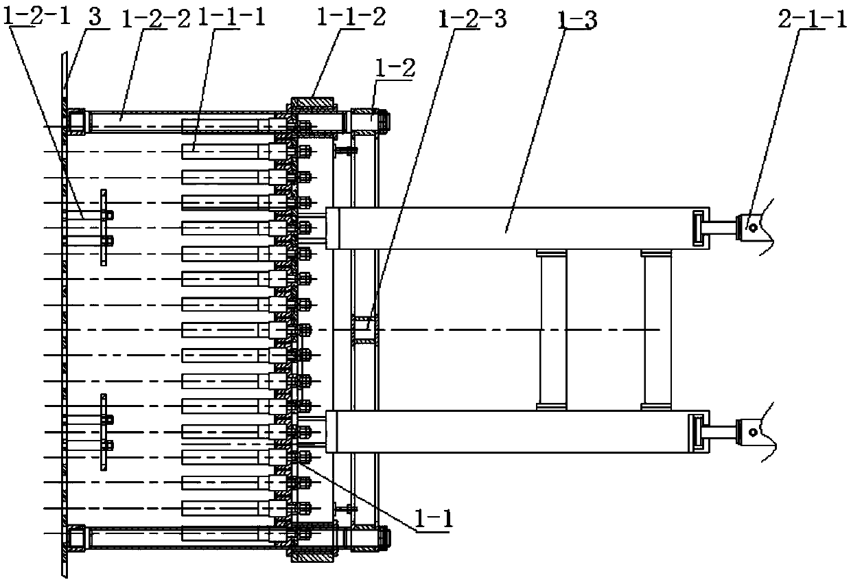
[0026] An automatic dredging device for leachate grid plate in a waste incineration power plant as described in the accompanying drawings, including a dredging actuator 1 and a mobile frame 2; the dredging actuator 1 includes a ejection structure 1-1 and a guiding structure 1 -2 and the transmission structure 1-3; the grid plate 3 is fixed on the wall 4; the plurality of dredging actuators 1 are installed on the grid plate 3, corresponding to the grid plate 3; the ejection The structure 1-1 is arranged corresponding to the grid hole; the ejection structure 1-1 can reciprocate along the guiding path of the guiding structure 1-2, perpendicular to the grid plate 3; the mobile frame 2 can move along the grid The distribution direction of the plates 3 moves; when the mobile frame 2 is displaced to the corresponding position of the dredging actuator 1, the ejection structure...


PUM


Abstract

The invention discloses an automatic dredging device for leachate grid plate in a waste incineration power plant, which comprises a dredging actuator and a mobile frame; the dredging actuator includes an ejection structure, a guiding structure and a transmission structure; the grid plate fixed on the wall; the several dredging actuators are installed on the grille plate, corresponding to the grille plate one by one; the ejection structure is set correspondingly to the grille hole; the ejection structure can be guided along the guide structure The path is reciprocating perpendicular to the grid plate; the mobile frame can move along the distribution direction of the grid plate; when the mobile frame is displaced to the corresponding position of the dredging actuator, it drives the ejection structure to move through the transmission structure; The invention uses hydraulic power components to dredge the leachate grid plate of the waste incineration power plant. The mechanism is simple and the degree of automation is high. It can replace the current purely manual construction method and significantly improve the operation efficiency and safety.

Description

technical field [0001] The invention relates to power plant equipment, in particular to an automatic dredging device for leachate grid plates in waste incineration power plants. Background technique [0002] Along with economic development, the process of urbanization is also accelerating. Garbage disposal has become a social problem that cannot be ignored. At present, due to the continuous and explosive increase in the amount of garbage, the original landfill is becoming increasingly saturated, and it is far from being able to meet the demand. Waste incineration power generation can effectively reduce the pollution and storage pressure caused by simple landfill. [0003] The moisture content of garbage in my country is relatively high, and the average moisture content of garbage is 30%-40%. In order to facilitate the smooth discharge of water in the garbage, the "Household Waste Incineration Power Generation Engineering Design Code" requires that the garbage storage in t...

Claims


Application Information

Patent Timeline
IPC IPC(8): C02F1/00C02F103/06
CPCC02F1/001C02F2303/14C02F2103/06
Inventor 赵士杰孙浩
Owner 徐州中矿长安科技有限公司
Why Eureka
Try Eureka