
An evaporation device

An evaporation and heating device technology, applied in vacuum evaporation plating, sputtering plating, ion implantation plating, etc., can solve the problems of cumbersome weighing steps and difficult replacement, and achieve convenient control, uniform heating, and improved control effect of ability

Active Publication Date: 2019-09-20
SHENZHEN CHINA STAR OPTOELECTRONICS SEMICON DISPLAY TECH CO LTD
View PDF11 Cites 0 Cited by
  • Summary
  • Abstract
  • Description
  • Claims
  • Application Information

AI Technical Summary

Problems solved by technology

[0005] The main technical problem to be solved by this application is to provide an evaporation device, which can solve the problems that the traditional evaporation equipment is not easy to replace the crucible and the weighing steps are cumbersome

Method used


Image

  • An evaporation device
  • An evaporation device
  • An evaporation device

Examples


Embodiment Construction

[0033] The following will clearly and completely describe the technical solutions in the embodiments of the present application. Obviously, the described embodiments are only some of the embodiments of the present application, rather than all the embodiments. Based on the embodiments in this application, all other embodiments obtained by persons of ordinary skill in the art without making creative efforts belong to the scope of protection of this application.

[0034] It is worth noting that the directional terms mentioned in this application, for example, "upper", "lower", "front", "rear", "left", "right", "inner", "outer", " "side", etc., are only referring to the directions of the attached drawings. Therefore, the direction terms used are for better and clearer description and understanding of the present application, rather than indicating or implying that the referred device or element must have a specific orientation. , are constructed and operate in a particular orienta...


PUM


Abstract

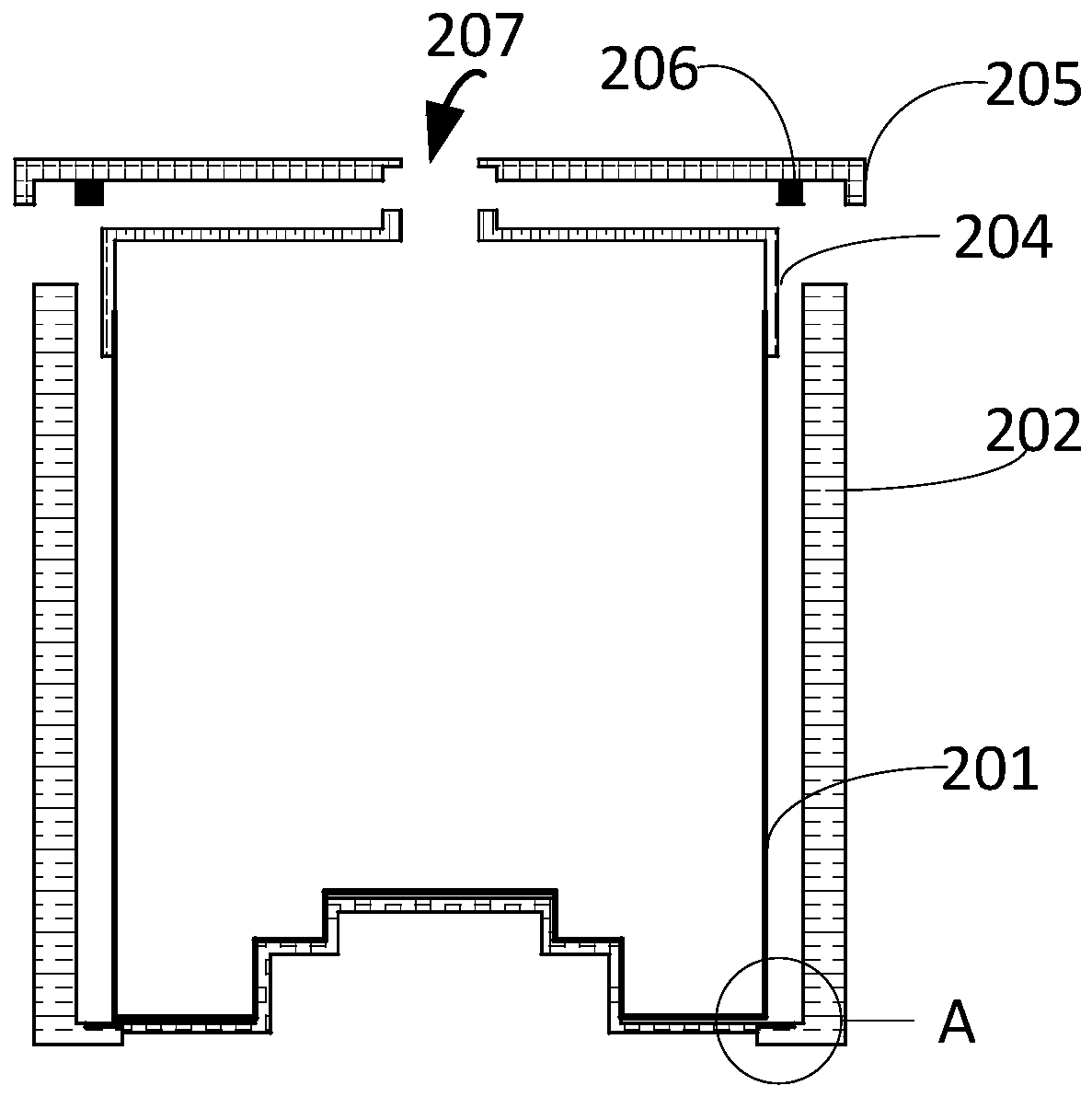
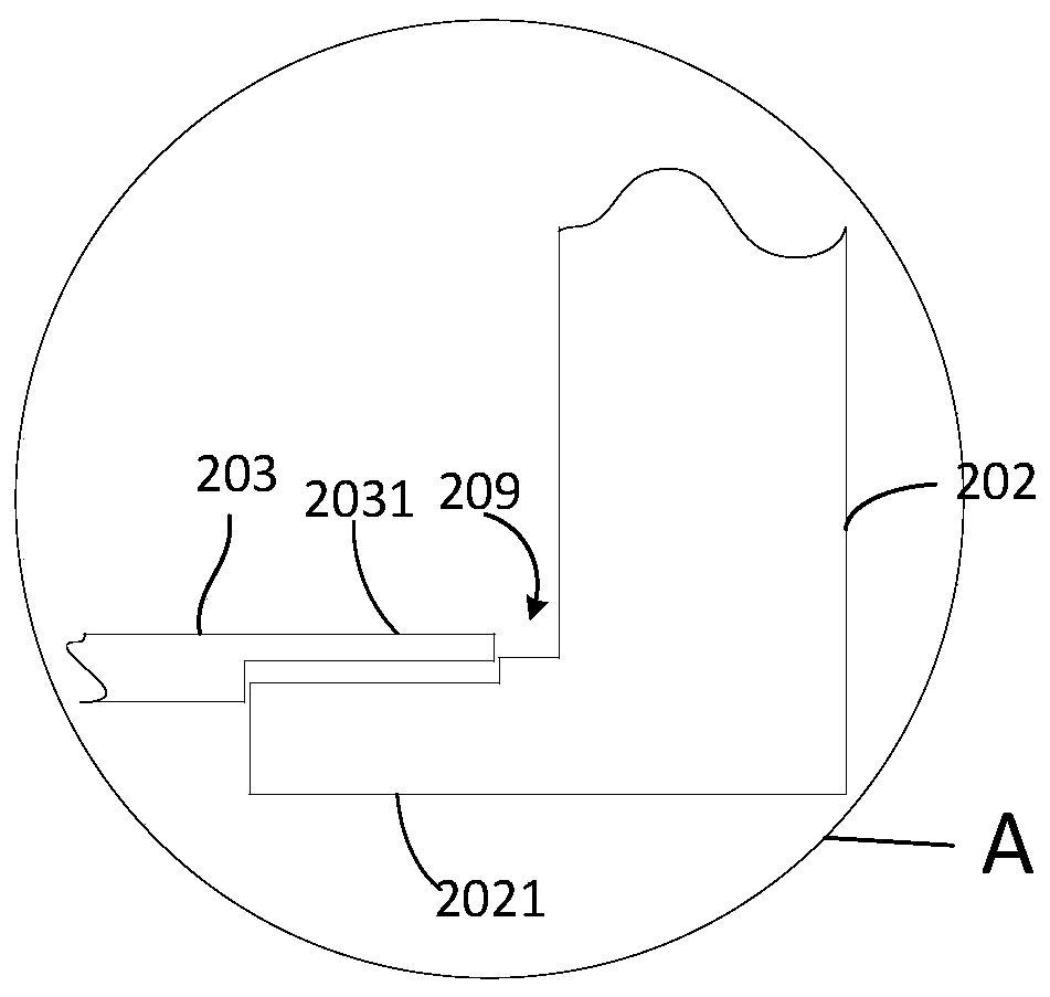
The present application relates to an evaporation device, which includes a crucible body, a side heating device arranged around the crucible body and a bottom heating device arranged below the crucible body; the bottom heating device can be move up and down along the height direction of the side heating device, and support the crucible main body to rise to a position higher than the side heating device. In this application, a heating device is provided at the bottom, so that the main body of the crucible can move up and down, thereby improving maintenance efficiency, shortening maintenance time, and reducing redundant working procedures.

Description

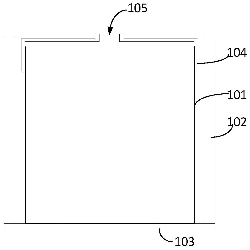
technical field [0001] The present application relates to the technical field of evaporation, and in particular to an evaporation device. Background technique [0002] OLED (Organic Light Emitting Diode, Organic Light Emitting Diode) has the advantages of all solid state, ultra-thin, no viewing angle limitation, fast response, room temperature operation, easy realization of flexible display and 3D display, etc., and is unanimously recognized as the mainstream technology of next-generation display. At present, the main way of making OLED devices is heating evaporation coating, which mainly uses a heating container to heat evaporation materials in a vacuum environment, so that sublimation or molten evaporation materials are vaporized at high temperature, and deposited on TFT (Thin Film) Transistor, thin film transistor) structure or anode structure on the substrate. [0003] Such as figure 1 As shown, the traditional evaporation crucible includes a crucible main body 101 and...

Claims


Application Information

Patent Timeline
Patent Type & Authority Patents(China)
IPC IPC(8): C23C14/24C23C14/12H01L51/56
CPCC23C14/12C23C14/24H10K71/164
Inventor 谭伟
Owner SHENZHEN CHINA STAR OPTOELECTRONICS SEMICON DISPLAY TECH CO LTD
Learn More