
A self-cleaning system for removing and purifying road surface rainwater and its installation method

A self-cleaning, rainwater technology, applied in waterway systems, chemical instruments and methods, water supply devices, etc., can solve problems such as difficult to discharge stagnant water in time, difficulties for pedestrians and vehicles to travel, water pollution in water areas, etc., to reduce capital investment and protect people Property, the effect of improving travel safety

Active Publication Date: 2020-02-18
ANHUI UNIVERSITY OF ARCHITECTURE
View PDF5 Cites 0 Cited by
  • Summary
  • Abstract
  • Description
  • Claims
  • Application Information

AI Technical Summary

Problems solved by technology

In particular, some cities do not pay attention to the influence of topography during the construction process, so that many low-lying places appear after the completion of urban road construction, and it is difficult to discharge the accumulated water in time after the heavy rain. The stagnant water is difficult to get rid of for a long time, causing great difficulties for pedestrians and vehicles to travel
Intersections are an extremely important part of urban roads. They are the places where vehicles and pedestrians gather, turn and evacuate. Most of the rainwater outlets are arranged equidistantly according to local customs without calculation. When drainage congestion occurs in a large area of ​​the city, it often takes a long time for the accumulated water to be drained, which brings huge hidden dangers to traffic safety.
[0003] At the same time, a large amount of rainwater containing suspended solids and harmful metal ions directly enters the urban pipe network through the rainwater outlet and is discharged into nearby waters, causing water pollution in the waters.

Method used


Image

  • A self-cleaning system for removing and purifying road surface rainwater and its installation method
  • A self-cleaning system for removing and purifying road surface rainwater and its installation method
  • A self-cleaning system for removing and purifying road surface rainwater and its installation method

Examples


Embodiment Construction

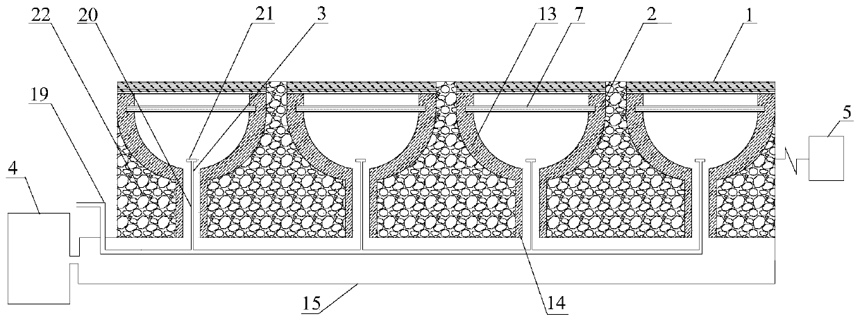
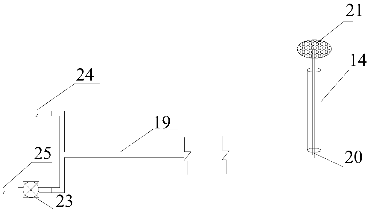
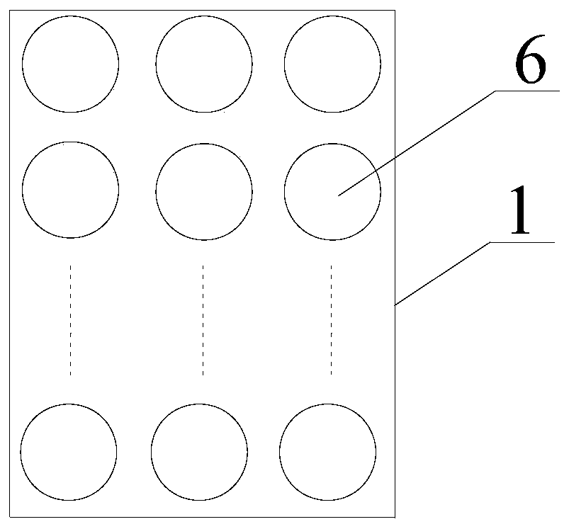
[0040] Referring to the accompanying drawings, a road surface rainwater removal and purification self-cleaning system includes several inspection well covers 1 arranged along the road width direction, a drainage device 2, a self-cleaning device 3, a collection, purification and reuse device 4, and a water accumulation depth warning device 5 The inspection shaft cover 1 is used as the driving road surface, and the drainage device 2 is located below the inspection shaft cover 1. A plurality of circular holes 6 are distributed on the inspection shaft cover 1. The inspection shaft cover 1 is rectangular, and the thickness of the inspection shaft cover 1 is according to the road surface. traffic flow determination;

[0041] The drainage device 2 comprises a diversion pool 13, a vertical drain pipe 14 connected to the bottom of the diversion pool 13, the diversion pool 13 is a long groove shape, and the cross section of the diversion pool 13 is a semicircle; A filter layer 7 is prov...


PUM


Abstract

The invention discloses a road surface rainwater removal and purification self-cleaning system and an installation method thereof, comprising several inspection shaft cover plates arranged along the road width direction, a drainage device, a self-cleaning device, a collection, purification and reuse device, and a water accumulation depth warning device; The device is located under the manhole cover, including a diversion pool, a vertical drain pipe, and a filter layer. The filter layer includes a base, alternately arranged filter plates, and telescopic plates. The self-cleaning device includes a dust removal main pipe and a dust removal vertical pipe. , sprinklers, collection, purification and reuse devices include sedimentation tanks, reservoirs, connecting pipes, rainwater nozzles, high-power water pumps, sponges, water depth early warning devices include rainfall detectors, water depth displays and PLC chip machines; drainage device drains The water capacity and layout quantity are calculated and determined according to the design displacement, and have three working modes; the system of the present invention has drainage function, road surface water warning function, water storage function, etc., and has self-cleaning function at the same time.

Description

technical field [0001] The invention belongs to the technical field of road drainage and application, in particular to a self-cleaning system and an installation method for rapid drainage, collection, purification and reuse of rainwater on low-lying road sections or sponge cities. Background technique [0002] With the rapid development of urbanization in China today, the urban population continues to increase, the industry develops rapidly, and the problem that municipal drainage system construction lags behind urban construction is becoming more and more prominent. In particular, some cities do not pay attention to the influence of topography during the construction process, so that many low-lying places appear after the completion of urban road construction, and it is difficult to discharge the accumulated water in time after the heavy rain. The stagnant water has been difficult to get rid of for a long time, causing great difficulties for pedestrians and vehicles to trav...

Claims


Application Information

Patent Timeline
Patent Type & Authority Patents(China)
IPC IPC(8): E01C11/22E03F5/04E03F5/06E03F5/10E03F5/14
CPCE01C11/225E03F5/0401E03F5/0404E03F5/06E03F5/10E03F5/14Y02A30/60
Inventor 王芳许培欣丁克伟刘凯钱如洋马志平韦璐陶明霞张祥
Owner ANHUI UNIVERSITY OF ARCHITECTURE
Learn More