
System and method for measuring concentration of impurities in solid

A measurement system and impurity concentration technology, applied in the field of quantum sensors, can solve the problems of low collection rate of escaped photons, limited detection efficiency, and low detection accuracy, and achieve the effects of improving detection efficiency, small size, and improving detection accuracy

Inactive Publication Date: 2018-03-16
BEIHANG UNIV
View PDF18 Cites 2 Cited by
  • Summary
  • Abstract
  • Description
  • Claims
  • Application Information

AI Technical Summary

Problems solved by technology

[0003] However, using the above optical method for detection, first, the shape of the diamond causes light to scatter, and the resulting scattering angle will form an optical waveguide effect. When it is reflected again, it will touch impurity particles that you do not want to measure, and new NV color centers will be detected. repeated excitation
Its measurement is not uniform due to the scattering behavior in it and the behavior of the optical waveguide
Secondly, the content of N and C in high-concentration samples is relatively high, but the size and quality of the two are different, so there will be stress, and then change from single crystal to polycrystal, resulting in a change in the refractive index, which is more conducive to the occurrence of scattering, thus It will also cause unnecessary impurities to be injected into the
Finally, due to the mutual occlusion between the color centers, they cannot be fully excited, and the collection rate of the escaped photons of the NV color centers is too low. The readout of a single spin requires tens of thousands of repeated detections, and the detection accuracy is very low. not tall
And because the optical device itself and the diamond refractive index limit the detection efficiency, the operation of this detection method is relatively cumbersome.

Method used


Image

  • System and method for measuring concentration of impurities in solid
  • System and method for measuring concentration of impurities in solid
  • System and method for measuring concentration of impurities in solid

Examples


Embodiment Construction

[0038] The following will clearly and completely describe the technical solutions in the embodiments of the present invention with reference to the accompanying drawings in the embodiments of the present invention. Obviously, the described embodiments are part of the embodiments of the present invention, not all of them. Based on the embodiments of the present invention, all other embodiments obtained by persons of ordinary skill in the art without making creative efforts shall fall within the protection scope of the present invention.

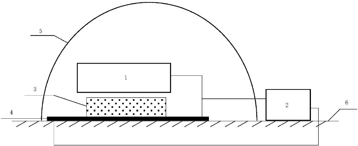
[0039] Such as figure 1 A measurement system for impurity concentration contained in a solid is shown, comprising: a spintronic magnetic sensor 4 , a magnetic field generating device 1 , a controller 2 and a solid 3 to be measured.

[0040] Wherein, the magnetic field generating device 1 is located on the side of the spintronic magnetic sensor 4 and is separated from the spintronic magnetic sensor 4 by a preset distance. The spintronic magnet...


PUM


Abstract

The invention relates to a system and method for measuring the concentration of impurities in a solid. The measuring system comprises a spinning electron magnetic sensor, a magnetic field generating device, and a controller. The magnetic field generating device is arranged on the lateral side of the spinning electron magnetic sensor, and a distance with a predetermined value exists between the magnetic field generating device and the spinning electron magnetic sensor. The spinning electron magnetic sensor detects the primary magnetic field strength of a magnetic field generated by the magneticfield generating device. A solid to be detected is arranged on the surface of the spinning electron magnetic sensor. The spinning electron magnetic sensor detects the current magnetic field strength.The controller determines the impurity concentration of the solid according to the corresponding relationship between preset magnetic field strengths and solid impurities concentrations, the primarymagnetic field strength, and the current magnetic field strength. The system and method have the advantages that the operation is simple, the method is easy to realize, and the detection efficiency and detection precision are both improved.

Description

technical field [0001] The invention relates to the technical field of quantum sensors, in particular to a measurement system and method for measuring the concentration of impurities contained in solids. Background technique [0002] NV in diamond – As a luminescent defect in a solid, the concentration of the color center directly affects the precision of its quantum sensing. Existing concentration detection usually adopts fluorescence intensity PL (Photoluminescence) detection method and optical detection magnetic resonance ODMR (Optical detection of magnetic resonance) detection method. [0003] However, using the above optical method for detection, first, the shape of the diamond causes light to scatter, and the resulting scattering angle will form an optical waveguide effect. When it is reflected again, it will touch impurity particles that you do not want to measure, and new NV color centers will be detected. Repeat excitation. It is not measured uniformly due to the...

Claims


Application Information

Patent Timeline
IPC IPC(8): G01N24/08
CPCG01N24/082
Inventor 袁珩李瑞媛张冀星卞国栋范鹏程杨笑盈李铭心
Owner BEIHANG UNIV
Learn More