Insulated gate bipolar transistor (IGBT) test circuit and method

A bipolar transistor and test circuit technology, applied in the field of power device reliability, can solve the problem of low accuracy of the IGBT reliability verification method for DC circuit breakers

Active Publication Date: 2018-03-16
GLOBAL ENERGY INTERCONNECTION RES INST CO LTD +1
View PDF14 Cites 19 Cited by
  • Summary
  • Abstract
  • Description
  • Claims
  • Application Information

AI Technical Summary

Problems solved by technology

[0005] Therefore, the technical problem to be solved by the present invention is to overcome the defect of low accuracy of the reliability verification method of DC circuit breaker IGBT when the line fault in the prior art

Method used


Image

  • Insulated gate bipolar transistor (IGBT) test circuit and method
  • Insulated gate bipolar transistor (IGBT) test circuit and method
  • Insulated gate bipolar transistor (IGBT) test circuit and method

Examples


Embodiment 1

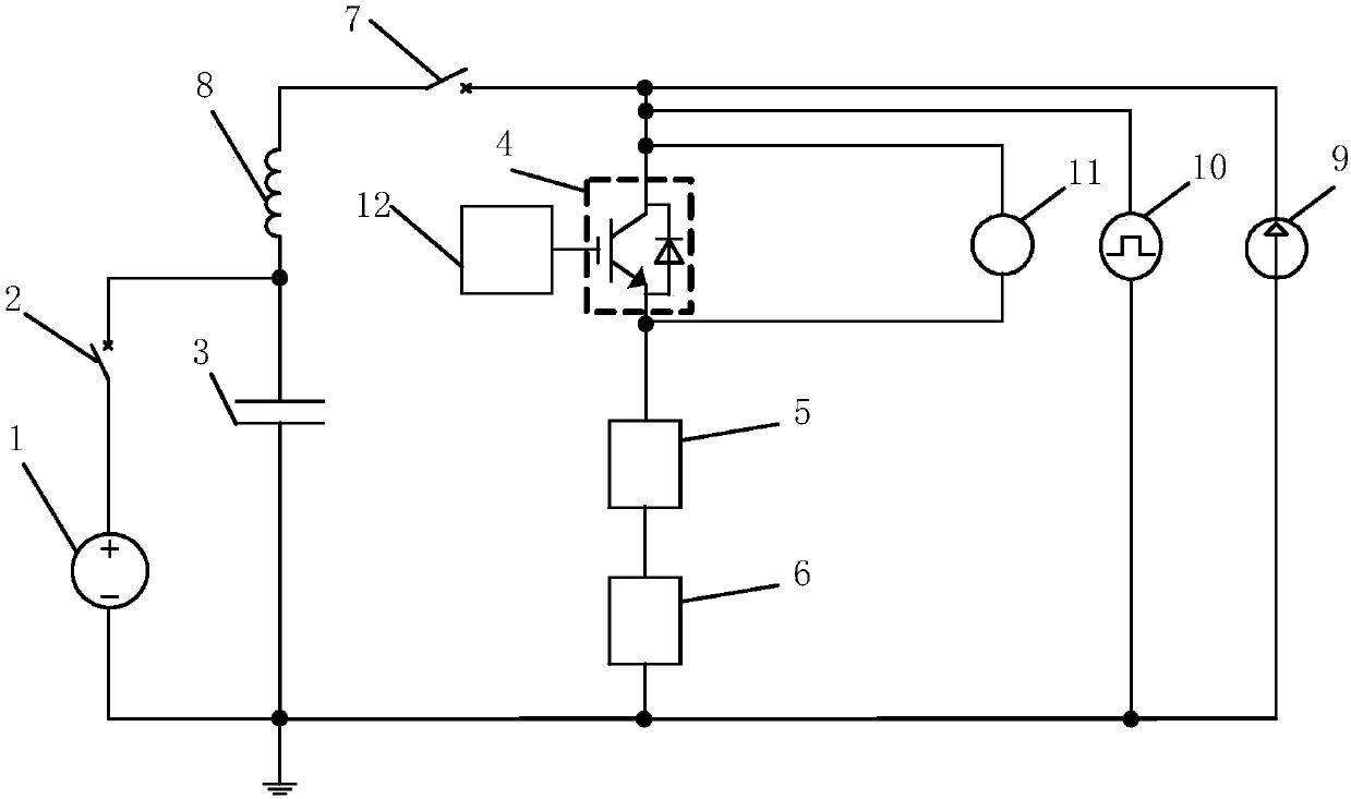
[0043] This embodiment provides an insulated gate bipolar transistor IGBT test circuit, such as figure 1 shown, including:

[0044] The first power supply 1, in this embodiment, the first power supply 1 is a controllable voltage source, which raises the voltage across the capacitor 3 to a predetermined voltage value, the predetermined voltage value is determined according to the withstand voltage level of the IGBT to be tested, and the predetermined voltage value It is necessary to ensure that a current waveform with a certain growth rate is generated within a few milliseconds during the capacitor discharge process to simulate the working waveform of a DC circuit breaker, that is, it can generate 4-6 times the rated current during this period, and the controllable voltage source has a voltage rise The advantages of controllable rate and simple operation; of course, in other embodiments, the first power source 1 is a controllable current source, which can be reasonably set as r...

Embodiment 2

[0054] This embodiment provides a method for testing an insulated gate bipolar transistor IGBT, using the test circuit in Embodiment 1, such as Figure 9 shown, including the following steps:

[0055] S1: Obtain the line failure rate and line maintenance time of the IGBT4 to be tested.

[0056] S2: Determine the preset number of times according to the failure rate of the line and the maintenance time of the line. In this embodiment, the preset number of times is set to 1000. Of course, in other embodiments, it can also be set to 500 or 2000. The more the preset times are, the more accurate the test result is, and it can be set reasonably as required.

[0057] S3: Obtain the initial value of the test. The test initial value includes the resistance value Rce between the collector and the emitter of the IGBT4 to be tested when the gate voltage of the IGBT4 to be tested is the first voltage and the collector and emitter of the IGBT4 to be tested when the gate voltage of the IGBT...


PUM


Abstract

The invention provides an insulated gate bipolar transistor (IGBT) test circuit and method. According to the circuit, a first switch and a first power source are connected in series to form a first series circuit; a capacitor and the first series circuit are connected in parallel to form a parallel circuit; a IGBT to be tested, a current harvester and a protection element are connected in series to form a second series circuit; the second series circuit is connected in parallel with a series circuit through a second switch, wherein the series circuit is composed of the parallel circuit and aninductor; a first current source and a second current source are connected in parallel with the second series circuit; a voltage detection unit is connected in parallel with the collector and emitterof the IGBT to be tested; and a control unit is connected with the gate of the IGBT to be tested. According to the insulated gate bipolar transistor (IGBT) test circuit and method, a circuit composedof the first power source, the first switch, the second switch, the inductor, and the capacitor is adopted to simulate short-circuit current during a fault; the IGBT to be tested is disconnected whencollector and emitter current collected by the current harvester reaches a preset value of the short-circuit current; Rce testing and Vce testing are performed; the operating condition of the IGBT ofa direct-current circuit breaker can be simulated more accurately, and a test result is closer to an actual fault condition; and test accuracy can be improved.

Description

technical field [0001] The invention relates to the field of reliability of power devices, in particular to an insulated gate bipolar transistor IGBT test circuit and method. Background technique [0002] In recent years, with the vigorous development of power electronics technology, the utilization efficiency and scale of renewable energy such as wind energy and solar energy have continued to expand, and the demand for renewable energy grid integration, distributed generation grid integration, and asynchronous AC grid interconnection has continued to rise. The advantages of Multi Termimal Voltage Source Converter High Voltage Direct Current (MTVSC-HVDC for short) are more prominent. However, the biggest problem for Multi Termimal High Voltage Direct Current (MT-HVDC for short) is that when a line fault occurs, the short-circuit current needs to be cut off very quickly on the DC side, which requires the use of a DC circuit breaker Cut off. [0003] DC circuit breakers are ...

Claims


Application Information

Patent Timeline
Patent Type & Authority Applications(China)
IPC IPC(8): G01R31/26
CPCG01R31/2608
Inventor 李尧圣李金元潘艳温家良崔梅婷王鹏
Owner GLOBAL ENERGY INTERCONNECTION RES INST CO LTD
Why Eureka
Try Eureka