Light conversion material packaging structure, backlight module and display device

A technology of light conversion materials and packaging structures, applied in optics, nonlinear optics, instruments, etc., can solve the problems of increased cost of diaphragms, expensive barrier films, complex processes, etc., and achieve the effect of reducing usage and reducing costs

Active Publication Date: 2020-12-25
TCL CHINA STAR OPTOELECTRONICS TECH CO LTD
View PDF17 Cites 0 Cited by
  • Summary
  • Abstract
  • Description
  • Claims
  • Application Information

AI Technical Summary

Problems solved by technology

[0004] In order to achieve a large viewing angle, the concept of a wide viewing angle is proposed. Some technologies are used in the backlight module, such as figure 1 As shown, by using the phosphor film fluorescent film layer 102 in the optical film assembly of the traditional backlight module, using the photoluminescent properties of the fluorescent film layer, the emitted light is isotropic and outgoing light, but the traditional fluorescent layer, especially the QD Film quantum dot film, in order to enhance its reliability, it is necessary to install barrier layers 101, 103 on its upper and lower surfaces to block water and oxygen. The cost of the barrier film is expensive, and the process is complicated, which greatly increases the cost of the film

Method used


Image

  • Light conversion material packaging structure, backlight module and display device
  • Light conversion material packaging structure, backlight module and display device
  • Light conversion material packaging structure, backlight module and display device

Examples


Embodiment Construction

[0026] In order to enable those skilled in the art to better understand the technical solutions of the present invention, the present invention will be further described in detail below in conjunction with the accompanying drawings and specific embodiments.

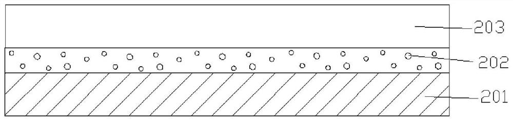
[0027] see figure 2 , in the embodiment of the light conversion material encapsulation structure of the present invention, the light conversion material 202 of the light conversion material encapsulation structure is coated on the diffusion plate 201, and the light conversion material 202 is also covered with a barrier layer 203. In this implementation In an example, the barrier layer may be PET (polyethylene terephthalate, polyethylene terephthalate PET barrier film), or contain materials such as silicon oxide and titanium oxide. Because the light conversion material 202 is generally sensitive to water vapor and oxygen, and is prone to failure during use, the barrier layer 203 is used to cover the light conversion mater...


PUM

PropertyMeasurementUnit
thicknessaaaaaaaaaa
particle diameteraaaaaaaaaa

Abstract

The invention provides a backlight module. The backlight module includes a light conversion material encapsulating structure, the light conversion material encapsulating structure consists of a diffusion plate and a light conversion material, the light conversion material is arranged on the diffusion plate and covered with a blocking layer, and the diffusion plate and the blocking layer seal the light conversion material to block moisture and oxygen. The structure can reduce usage of blocking layers, decrease the cost and have a wide viewing angle, and therefore the light emitting angle of thebacklight module is greater than 120 degrees so that a display device with the backlight module can achieve the effect of a wide viewing angle.

Description

technical field [0001] The invention relates to the technical field of liquid crystal panel display, in particular to a light conversion material packaging structure for a backlight module, a backlight module and a display device. Background technique [0002] Liquid crystal display (Liquid Crystal Display, LCD) has the characteristics of light and thin, low power consumption, and no radiation, and has now occupied a dominant position in the field of flat-panel display. , laptops, mobile phones, digital cameras and other electronic equipment. [0003] Most of the backlights used in LCDs at this stage are LEDs. Take the side-type backlight as an example. A certain number of optical films are used to cover mura (spots with uneven brightness on the display device) or to increase brightness. The inventor of the present application has found in long-term research and development that although the brightness of the display device can be greatly improved in the existing design, t...

Claims


Application Information

Patent Timeline
Patent Type & Authority Patents(China)
IPC IPC(8): G02F1/13357
CPCG02F1/133606G02F1/13362G02F1/133607G02F1/133614
Inventor 常建宇李泳锐萧宇均张简圣哲
Owner TCL CHINA STAR OPTOELECTRONICS TECH CO LTD
Why Eureka
Try Eureka