Exponential mapping-based design method of retro-reflective optical invisibility cloak

A design method and exponential technology, applied in the field of transformation optics, to achieve the effect of simple form and convenient manufacturing

Active Publication Date: 2018-03-16
NANJING UNIV OF SCI & TECH
View PDF1 Cites 8 Cited by
  • Summary
  • Abstract
  • Description
  • Claims
  • Application Information

AI Technical Summary

Problems solved by technology

[0003] The purpose of the present invention is to provide a retroreflective optical invisibility cloak design method based on index mapping to solve the problem of stealth of objects and the extraction of retroreflection information from the rear of objects

Method used


Image

  • Exponential mapping-based design method of retro-reflective optical invisibility cloak
  • Exponential mapping-based design method of retro-reflective optical invisibility cloak
  • Exponential mapping-based design method of retro-reflective optical invisibility cloak

Examples


Embodiment Construction

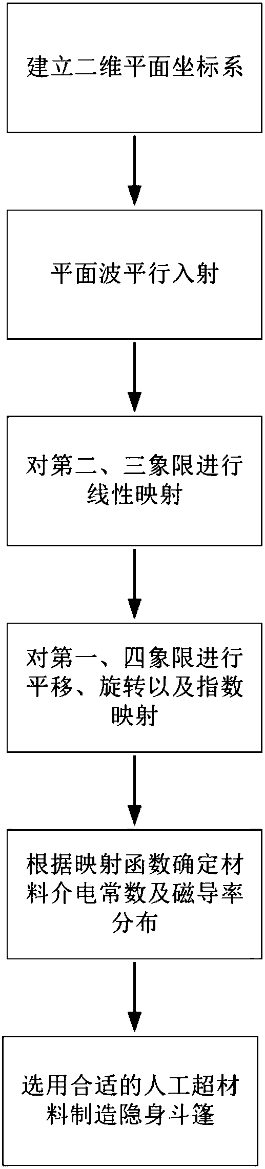
[0019] combine figure 2 , the present invention is based on the method for the design of the retroreflective optical cloak of index mapping, and the steps are as follows:

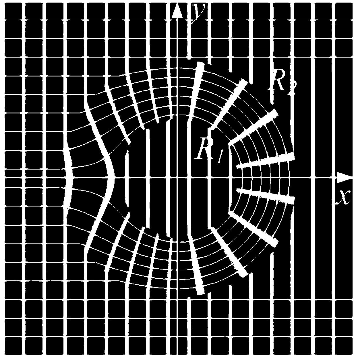
[0020] Step 1: If figure 1 The two-dimensional x-y plane coordinate system is established as shown, and the radius is R 2 Coordinates are conformally mapped within the range of . R 2 The value is determined according to actual needs, such as 5-10 microns. figure 1 It mainly explains the establishment of the coordinate system and the simulation of the trajectory of the light passing through the cloak.

[0021] Step 2: Parallel incidence of a beam of plane waves from the negative direction of the x-axis to the positive direction of the x-axis. For example, the wavelength of a beam of plane waves can be 500-700 nanometers.

[0022] Step 3: Perform linear mapping in polar coordinates on the second and third quadrants of the coordinate system where the invisibility cloak is located, so that the radius ran...


PUM


Abstract

The invention discloses an exponential mapping-based design method of a retro-reflective optical invisibility cloak. Firstly, a two-dimensional x-y plane coordinate system is established, and conformal mapping is carried out on coordinates in a range of which a radius is R2; a plane wave is emitted in parallel from an x-axial negative direction to an x-axial positive direction; linear mapping under polar coordinates is carried out on a second quadrant and a third quadrant of the coordinate system, where the invisibility cloak is located, to enable the radius range to be mapped to R1-R2 from 0-R2; a first quadrant of the coordinate system is mapped, and a fourth quadrant of the coordinate system is mapped; then a metric tensor of deformed space and a dielectric tensor and a permeability tensor of an impedance matching medium provided by transformation optics are calculated according to the impedance matching medium and equivalent relationships of space geometry; and finally, a Z component in the permeability tensor is normalized, and an artificial metamaterial is selected and used according to dielectric tensor distribution and permeability distribution to manufacture the optical invisibility cloak. The method solves problems of invisibility for objects and extraction of information of retro-reflection behind the objects.

Description

technical field [0001] The invention belongs to the technical field of transformation optics, and in particular relates to a design method for a retroreflective optical invisibility cloak based on index mapping. Background technique [0002] Since Pendry et al. proposed the transformation optics theory in 2006, various transformation optics-based invisibility cloak design methods have been continuously proposed. For impedance matching media, the dielectric tensor and permeability tensor have the same distribution form. According to the form invariance of Maxwell's equations, the effect of such impedance matching media on the electromagnetic field is equivalent to the geometric transformation of space. This brings up a new way of thinking for people to design invisibility cloaks. Through the specific transformation of the design space, the light can achieve a certain bending effect, avoiding the diffraction by the invisible objects, and then according to the space transformat...

Claims


Application Information

Patent Timeline
Patent Type & Authority Applications(China)
IPC IPC(8): G06F17/50
CPCG06F30/20
Inventor 辛煜卢斌韩硕吴钰李扬彦
Owner NANJING UNIV OF SCI & TECH
Why Eureka
Try Eureka