
High voltage prevention high frequency transformer

A high-voltage, high-frequency, transformer technology, applied in the field of transformers, can solve problems such as affecting normal work, uneven placement of transformers, and difficulty in operation, so as to avoid potential safety hazards, improve production efficiency, and avoid fixed methods.

Active Publication Date: 2018-03-16
NINGBO ZHONGCE E T ELECTRONICS
View PDF6 Cites 0 Cited by
  • Summary
  • Abstract
  • Description
  • Claims
  • Application Information

AI Technical Summary

Problems solved by technology

The current high-frequency transformer manufacturing method is to directly wind the primary enameled wire on one side of the magnetic ring on a magnetic ring, and the secondary enameled wire is wound on the other side of the magnetic ring, and then line the primary enameled wire and the secondary enameled wire. A piece of glass fiber board, the glass fiber board is usually fixed on the magnetic ring by epoxy dispensing, so that the primary enameled wire and the secondary enameled wire of the high-frequency transformer produced in this way will have direct contact with the magnetic ring, although there is glass between the primary and secondary enameled wire The fiberboard is separated, and this structure has the following disadvantages: during the winding process, the enameled wire sheath is easily cut and damaged by the glass fiberboard, or by the contour of the magnetic ring itself, which will make the product's primary enameled wire and There is a safety hazard in the secondary enameled wire, which affects the reliability of the product; 2. It is fixed by epoxy dispensing, which is very complicated to operate and affects production efficiency; 3. The lead-out end of the enameled wire is not positioned, and when the customer inserts the high-frequency transformer into the circuit board It will be difficult to operate and affect customer experience; 4. The lead-out end of the enameled wire is not positioned, and the transformer inserted into the circuit board will be placed unevenly, affecting normal work

Method used


Image

  • High voltage prevention high frequency transformer
  • High voltage prevention high frequency transformer
  • High voltage prevention high frequency transformer

Examples


Embodiment Construction

[0018] The invention will be further described below with reference to the accompanying drawings and in combination with specific embodiments, so that those skilled in the art can implement it by referring to the description, and the protection scope of the present invention is not limited to the specific embodiments.

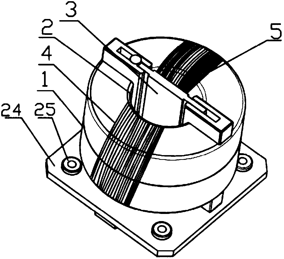
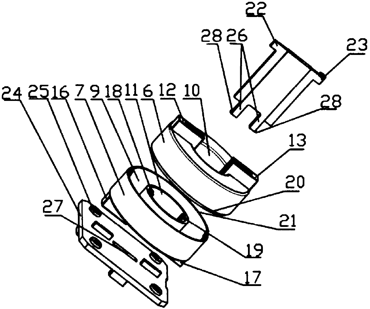
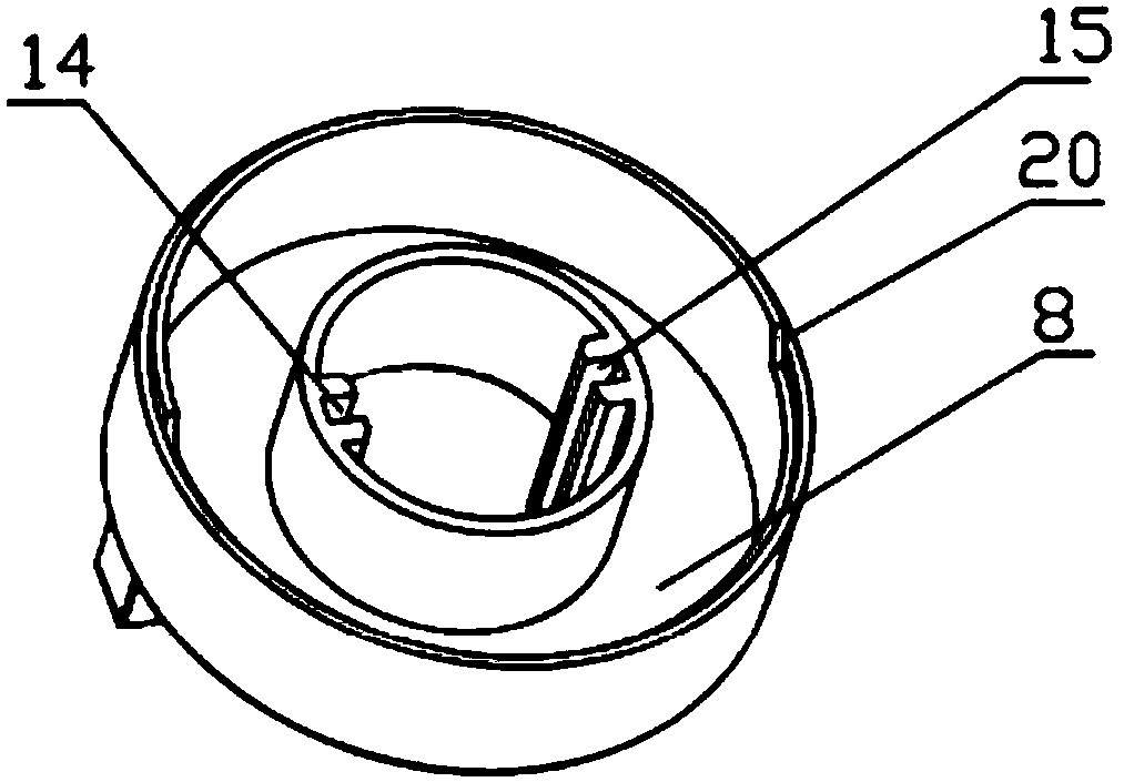
[0019] The invention relates to an anti-high voltage and high frequency transformer, such as figure 1 As shown, it includes a casing 1 and a ring through hole 2 arranged on the vertical center axis of the casing. The inside of the casing 1 includes an inner cavity for placing a magnetic ring. The movable insert 3 of the hole 2, the primary winding 4 located on one side of the insert and wound on the shell 1, and the secondary winding 5 located on the other side of the insert 3 and wound on the shell 1, the lead-out end of the winding Enter from one opening of the ring through hole 2 and exit from the other opening, and the winding is wound on the shell 1 round ...


PUM


Abstract

The invention relates to a high voltage prevention high frequency transformer. The high voltage prevention high frequency transformer comprises a shell and an annular through hole formed in the vertical center axis of the shell, the inside of the shell comprises an inner cavity for placing a magnetic ring, and the high voltage prevention high frequency transformer further comprises a movable inserting sheet capable of penetrating through the annular through hole, a primary winding which is located at one side of the inserting sheet and is wound on the shell and a secondary winding which is located at the other side of the inserting sheet and is wound on the shell. The magnetic ring of the high frequency transformer is directly provided with the shell, so that the magnetic ring is embeddedin the inner cavity of the shell, then the windings are wound on the shell, so that the magnetic ring material is completely spaced from the windings, the occurrence that the windings are damaged is avoided, the potential safety hazard is avoided, and the reliability of the product is improved; the primary winding and the secondary winding are spaced through the movable inserting sheet, the fixingmode of epoxy glue dispensing is avoided, the operation is convenient, and the production efficiency is improved.

Description

technical field [0001] The invention relates to the technical field of transformers, in particular to an anti-high voltage and high frequency transformer. Background technique [0002] High-frequency transformer is a power transformer whose operating frequency exceeds intermediate frequency (10kHz). It is mainly used as a high-frequency switching power transformer in high-frequency switching power supplies, and also used in high-frequency inverter power supplies and high-frequency inverter welding machines as high-frequency inverters. According to different uses, the magnetic core material and structure of the transformer will be different. The current high-frequency transformer manufacturing method is to directly wind the primary enameled wire on one side of the magnetic ring on a magnetic ring, and the secondary enameled wire is wound on the other side of the magnetic ring, and then line the primary enameled wire and the secondary enameled wire. A piece of glass fiber boa...

Claims


Application Information

Patent Timeline
Patent Type & Authority Applications(China)
IPC IPC(8): H01F27/24H01F27/30H01F19/04
CPCH01F19/04H01F27/24H01F27/306
Inventor 黄力瞿文军赵辉
Owner NINGBO ZHONGCE E T ELECTRONICS
Learn More