power generation device

A power generation device and extreme position technology, applied in electromechanical devices, electric components, electrical components, etc., can solve the problems of pollution service life, frequent replacement, etc., achieve long service life, solve short service life, and improve the effect of user experience

Active Publication Date: 2019-10-08
BYD CO LTD
View PDF3 Cites 0 Cited by
  • Summary
  • Abstract
  • Description
  • Claims
  • Application Information

AI Technical Summary

Problems solved by technology

[0004] The purpose of this disclosure is to provide a power generation device, which is used to solve the problems of environmental pollution, short service life and frequent replacement when low-power electronic products use ordinary batteries in the prior art

Method used


Image

  • power generation device
  • power generation device
  • power generation device

Examples


Embodiment Construction

[0046] Reference will now be made in detail to the exemplary embodiments, examples of which are illustrated in the accompanying drawings. When the following description refers to the accompanying drawings, the same numerals in different drawings refer to the same or similar elements unless otherwise indicated. The implementations described in the following exemplary examples do not represent all implementations consistent with the present disclosure. Rather, they are merely examples of apparatuses and methods consistent with aspects of the present disclosure as recited in the appended claims.

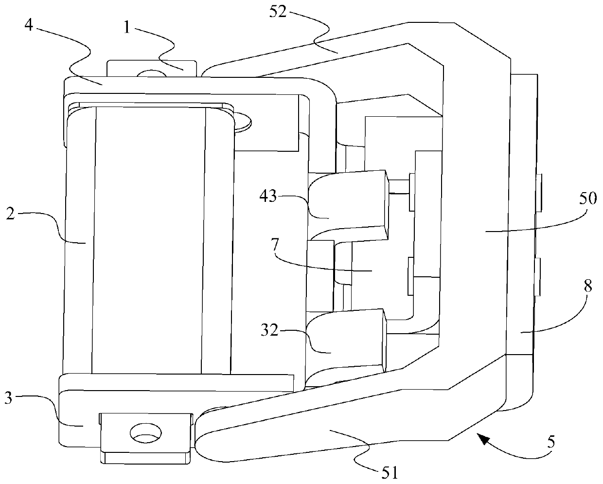
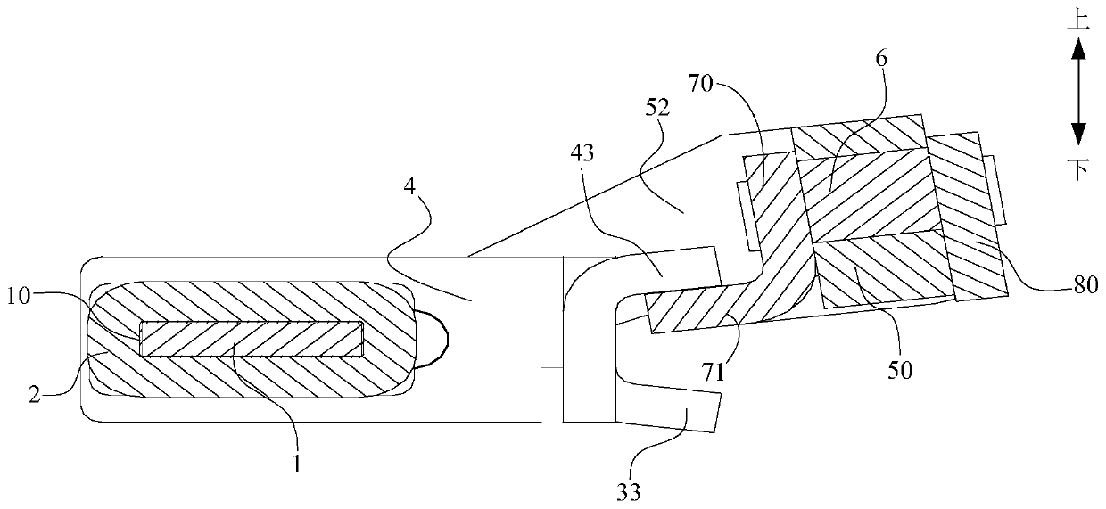
[0047] Please refer to figure 1 and image 3 , figure 1 is a schematic structural diagram of a power generating device shown according to an exemplary embodiment, image 3 It is a schematic cross-sectional view of a rocker arm of a power generation device at a first extreme position according to an exemplary embodiment. Such as figure 1 and image 3 As shown, the power generating...


PUM


Abstract

The invention discloses a power generation device. The power generation device includes a winding core, a winging coil coiling the winding core, a left core connected to the left end of the winding core, a right core connected to the right end of the winding core, a rocker arm including two movable connection parts connected to the left core and the right core respectively in a movable manner anda fixed connection part connected to the movable connection part, a permanent magnet arranged on the rocker arm, an inner pole piece and an outer pole piece connected to the two electrodes of the permanent magnet. When the rocker arm swings to a first extreme position along a first direction under the drive of external forces, the inner pole piece is in contact with the right core, and the outer pole piece is in contact with the left core. When the rocker arm swings to a second extreme position along a second direction which is opposite to the first direction under the drive of external force,the inner pole piece is in contact with the left core and the outer pole is in contact with the right core. The power generation device provided by the invention solves problems that a conventional battery adopted by a low power consumption electronic product is short in service life and requires frequent change.

Description

technical field [0001] The present disclosure relates to the field of electromagnetic power generation, and in particular, to a power generation device. Background technique [0002] At present, with people's attention to environmental protection, and the country's more and more policy support for green energy, environmental protection enterprises and innovative products, people's demand for low-carbon, green and environmental protection products is increasing. Environmentally friendly electronics The product market is also growing. [0003] Due to the complicated and inconvenient installation lines of wired switches, the high cost, and the inconvenient maintenance of the lines, wireless switches are becoming more and more popular. However, many current wireless switches use nickel-cadmium batteries to provide electric energy, and nickel-cadmium batteries will pollute the environment due to the presence of heavy metals, and it will be inconvenient to replace the batteries w...

Claims


Application Information

Patent Timeline
Patent Type & Authority Patents(China)
IPC IPC(8): H02K7/18F03G5/06
Inventor 杨建锋肜卿蒋丛华周虎
Owner BYD CO LTD
Why Eureka
Try Eureka