
PCB (Printed Circuit Board) printing bearing jig

A PCB board and fixture technology, applied in the field of PCB board printing bearing fixtures, can solve the problems of increased printing time, easy damage to PCB boards, waste of resources, etc., and achieves the effect of wide application, convenient use and improved efficiency.

Inactive Publication Date: 2018-03-16
中山市标致电子科技有限公司
View PDF0 Cites 2 Cited by
  • Summary
  • Abstract
  • Description
  • Claims
  • Application Information

AI Technical Summary

Problems solved by technology

In the prior art, there are still many deficiencies in the PCB printing bearing fixture, which has a single function and no drying function, which increases the time required for printing; the existing PCB printing bearing fixture has a fixed structure and cannot be used according to the PCB The specifications of the board are used to replace parts, and the versatility is insufficient; at the same time, the existing PCB board printing bearing fixture has a poor fixing effect on the PCB board, and is easy to damage the PCB board, resulting in waste of resources, so a new type of PCB board printing bearing is urgently needed Fixtures to solve the above problems

Method used


Image

  • PCB (Printed Circuit Board) printing bearing jig
  • PCB (Printed Circuit Board) printing bearing jig
  • PCB (Printed Circuit Board) printing bearing jig

Examples


Embodiment Construction

[0024] In order to make the technical means, creative features, goals and effects achieved by the present invention easy to understand, the present invention will be further described below in conjunction with specific embodiments.

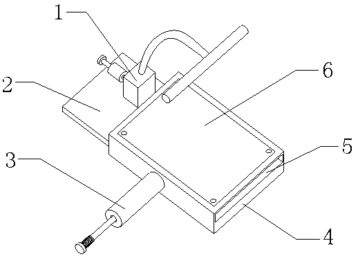
[0025] see Figure 1-Figure 4 , the present invention provides a technical solution: a PCB board printing bearing jig, including a device main body, a quick drying mechanism 1, an air pressure fixing mechanism 3, and a disassembly and assembly mechanism 6. The device main body includes a placement board 2, a box body 4 and a square Groove 5, place plate 2 is installed on box body 4 left end faces, square groove 5 offers on box body 4 right end faces.

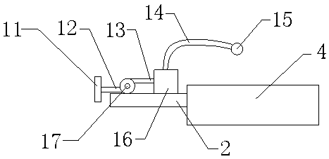
[0026] The fast drying mechanism 1 includes a wide mouth mask 11, an air intake pipe 12, an air delivery pipe 13, a gooseneck pipe 14, an air distribution pipe 15, a heating box 16 and a fan 17, and the fan 17 is installed on the left side of the upper end surface of the placement plate 2, and the h...


PUM


Abstract

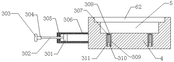
The invention provides a PCB (Printed Circuit Board) printing bearing jig. The PCB printing bearing jig comprises an air inlet pipe, a gooseneck pipe, an air distribution pipe, a heating tank, a piston one, a threaded rod, a round hole, ejector rods, rubber discs and pistons II, wherein the heating tank is arranged at the right side of the upper end surface of a placement plate, the right end of the air inlet pipe is connected with a draught fan, the air distribution pipe is arranged at the upper side of a box body, and the left end of the gooseneck pipe is connected with the heating tank, sothat through the design, a drying function of the PCB printing bearing jig is added, and the purpose of quickly drying a PCB by the PCB printing bearing jig can be realized; the piston I is arranged in an air cylinder, a push-pull board is arranged on the left end of the threaded rod, the round holes are formed in the left end surface of the air cylinder, the pistons II are arranged in a cylinder,and the upper ends of the ejector rods are fixed to middle positions of the lower end surfaces of the rubber discs, so that through the design, the purpose of fixing the PCB by utilizing air pressureis realized. The PCB printing bearing jig provided by the invention is convenient to use, wide in application range, good in stability and high in reliability.

Description

technical field [0001] The invention relates to a PCB printing bearing jig, which belongs to the technical field of PCB printed circuit boards. Background technique [0002] Fixtures are a large class of tools for woodworking, ironwork, fitter, machinery, electric control and other handicrafts, mainly as a tool to assist in controlling position or movement (or both). The classification of fixtures can be divided into three categories: process assembly fixtures, project test fixtures and circuit board test fixtures. [0003] In the general PCB manufacturing process, it is necessary to use a jig to support the board during printing to complete the printing ink on the PCB board to achieve the purpose of improving production efficiency. In the prior art, there are still many deficiencies in the PCB printing bearing fixture, which has a single function and no drying function, which increases the time required for printing; the existing PCB printing bearing fixture has a fixed st...

Claims


Application Information

Patent Timeline
IPC IPC(8): H05K3/12
CPCH05K3/1283
Inventor 董彭李文勇
Owner 中山市标致电子科技有限公司
Learn More