Multi-small-round-steel-bar punching mechanism for punch

A punching machine and round steel technology, which is applied in the field of multiple punching mechanisms for small round steel rods for punching machines, can solve the problems that the punching holes of the round guide sleeve are on the same axis, the processing is difficult, and the punching holes are discarded. Achieve the effect of improving device utilization rate and production cutting efficiency, improving cutting efficiency and reducing quantity

Pending Publication Date: 2018-03-20
PENGXI HEYE HI TECH
View PDF0 Cites 0 Cited by
  • Summary
  • Abstract
  • Description
  • Claims
  • Application Information

AI Technical Summary

Problems solved by technology

And the processing of the "lower mold base" must ensure sufficient size and position accuracy between the installation hole of the "round guide sleeve", the screw installation hole and the lower "die base bearing surface"; otherwise, due to the small hole and the "down punch" "Knife" is deformed by heat treatment, it is difficult to ensure that the punching holes of the "round guide sleeve" and the "lower punching knife" are on the same axis, and the guide material of the "round guide sleeve" is often increased due to the different axes of the punching holes during use. The hole diameter makes the feeding not smooth, and the punching hole is seriously abandoned
Therefore, the design of the "lower mold seat" especially the "lower punch knife" is difficult and expensive to process.

Method used


Image

  • Multi-small-round-steel-bar punching mechanism for punch
  • Multi-small-round-steel-bar punching mechanism for punch
  • Multi-small-round-steel-bar punching mechanism for punch

Examples


Embodiment 1

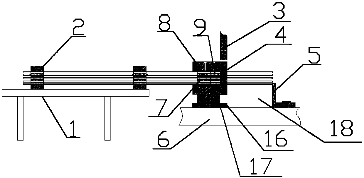
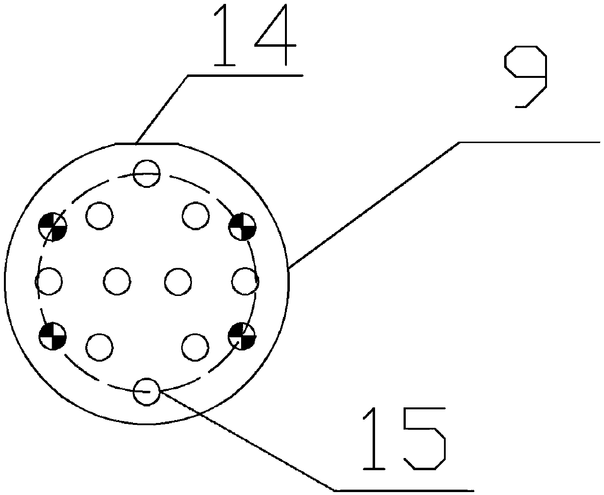
[0029] like figure 1 and 2As shown, the present embodiment provides a multi-branch punching mechanism for small round steel rods for a punching machine, including a lower die base 17, a loading rack 1 and a punch workbench 6, and the lower die base 17 is located at the punch workbench 6 The upper part of the upper part, the loading rack 1 is located on one side of the punch table 6, the lower mold base 17 is provided with a guide sleeve 7, and the guide sleeve 7 is correspondingly provided with a lower punching knife 9, the The lower punching knife 9 is provided with a punching hole 15, the diameter of the punching hole 15 is consistent with the inner diameter of the passage of the guide sleeve 7, and the punching hole 15 is not on the same vertical line as the adjacent punching hole 15. On, the top of the lower punching knife 9 is provided with a fixed surface 14, the lower punching knife 9 is fixed on the middle part of the outer side of the lower mold base 17, the front en...

Embodiment 2

[0031] like Figure 1-3 As shown, the present embodiment provides a multi-branch punching mechanism for small round steel rods for a punching machine, including a lower die base 17, a loading rack 1 and a punch workbench 6, and the lower die base 17 is located at the punch workbench 6 The upper part of the upper part, the loading rack 1 is located on one side of the punch table 6, the lower mold base 17 is provided with a guide sleeve 7, and the guide sleeve 7 is correspondingly provided with a lower punching knife 9, the The lower punching knife 9 is provided with a punching hole 15, the diameter of the punching hole 15 is consistent with the inner diameter of the passage of the guide sleeve 7, and the punching hole 15 is not on the same vertical line as the adjacent punching hole 15. On, the top of the lower punching knife 9 is provided with a fixed surface 14, the lower punching knife 9 is fixed on the middle part of the outer side of the lower mold base 17, the front end o...

Embodiment 3

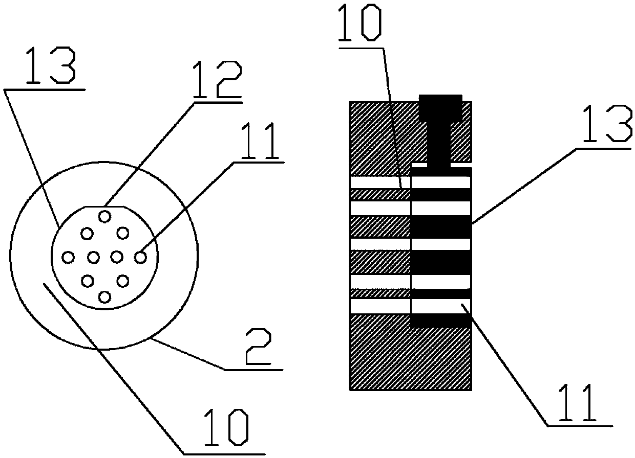
[0034] like Figure 1-4 As shown, the present embodiment provides a multi-branch punching mechanism for small round steel rods for a punching machine, including a lower die base 17, a loading rack 1 and a punch workbench 6, and the lower die base 17 is located at the punch workbench 6 The upper part of the upper part, the loading rack 1 is located on one side of the punch table 6, the lower mold base 17 is provided with a guide sleeve 7, and the guide sleeve 7 is correspondingly provided with a lower punching knife 9, the The lower punching knife 9 is provided with a punching hole 15, the diameter of the punching hole 15 is consistent with the inner diameter of the passage of the guide sleeve 7, and the punching hole 15 is not on the same vertical line as the adjacent punching hole 15. On, the top of the lower punching knife 9 is provided with a fixed surface 14, the lower punching knife 9 is fixed on the middle part of the outer side of the lower mold base 17, the front end o...


PUM

PropertyMeasurementUnit
Thicknessaaaaaaaaaa
Thicknessaaaaaaaaaa

Abstract

The invention discloses a multi-small-round-steel-bar punching mechanism for a punch, and relates to the technical field of machining. The technical problems that in the prior art, the punching die machining difficulty is large, and the production efficiency is low are solved. The multi-small-round-steel-bar punching mechanism comprises a lower die base, a feeding frame and a punch workbench. Thelower die base is located at the upper portion of the punch workbench. The feeding frame is located on one side of the punch workbench. A material guiding sleeve is arranged in the lower die base andcorrespondingly provided with a lower punching cutter provided with punching holes. The diameter of the punching holes is consistent with the inner diameter of a material guiding sleeve channel. The punching holes and the adjacent punching holes are not located in the same longitudinal straight line in the vertical direction. Each of the top and the corresponding lower portion of the lower punching cutter is provided with a fixing face. The lower punching cutter is fixed to the middle portion of the outer side face of the lower die base. A front baffle is arranged on the front end face of thelower punching cutter. The top of the lower punching cutter is correspondingly provided with an upper punching cutter. The integral staggered fastening manner is adopted in the multi-small-round-steel-bar punching mechanism, one cutter is adopted for punching multiple pieces, so that the production efficiency is greatly improved, and the multi-small-round-steel-bar punching mechanism is mainly applied to cutting of small round steel bars.

Description

technical field [0001] The invention relates to the technical field of mechanical processing, and more specifically relates to a multi-piece punching mechanism of small round steel rods for a punching machine. Background technique [0002] Straight round bars with a diameter of 3-12 mm generally need to be punched and cut into sections, which are used in a large amount and have a wide range of applications. At present, the punching mechanism for straight small round steel rods has the disadvantages of complex mold making and low punching efficiency. In the prior art, when the "lower punching knife" was installed, one of the punching holes was just on the same axis as the hole of the "circular material guide sleeve", and the round bar was smoothly exported for punching. When the hole is worn, remove the "lower punching knife" and rotate the lower punching knife so that the unworn punching hole corresponds to the "round guide sleeve", and then punch again until all the punchi...

Claims


Application Information

Patent Timeline
IPC IPC(8): B21D28/02B21D28/14B21D28/04B21D43/00B21D43/26
CPCB21D28/02B21D28/04B21D28/14B21D43/003B21D43/26
Inventor 胡晓兰汤文其何洲明刘金枝
Owner PENGXI HEYE HI TECH
Why Eureka
Try Eureka