
Plate shearing machine material guiding plate structure

A material guide plate and shearing machine technology, which is applied in the direction of shearing devices, shearing machine accessories, metal processing equipment, etc., can solve the problems of reducing the shearing efficiency of metal sheets, inconvenient cutting for operators, and troublesome operators , to improve cutting efficiency, save time and avoid waste

Inactive Publication Date: 2018-03-20
陈党照
View PDF0 Cites 2 Cited by
  • Summary
  • Abstract
  • Description
  • Claims
  • Application Information

AI Technical Summary

Problems solved by technology

[0004] Aiming at the deficiencies of the prior art, the present invention provides a material guide plate structure of a shearing machine, which has the advantages of being convenient for positioning thin metal sheets, and solves the problem of common shearing machines positioning thin metal sheets. The sheet is easy to bulge and it is inconvenient for the operator to cut it, which brings trouble to the operator and reduces the shearing efficiency of the metal sheet

Method used


Image

  • Plate shearing machine material guiding plate structure
  • Plate shearing machine material guiding plate structure
  • Plate shearing machine material guiding plate structure

Examples


Embodiment Construction

[0021] The following will clearly and completely describe the technical solutions in the embodiments of the present invention with reference to the accompanying drawings in the embodiments of the present invention. Obviously, the described embodiments are only some, not all, embodiments of the present invention. Based on the embodiments of the present invention, all other embodiments obtained by persons of ordinary skill in the art without making creative efforts belong to the protection scope of the present invention.

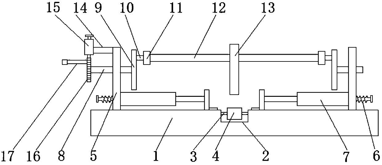
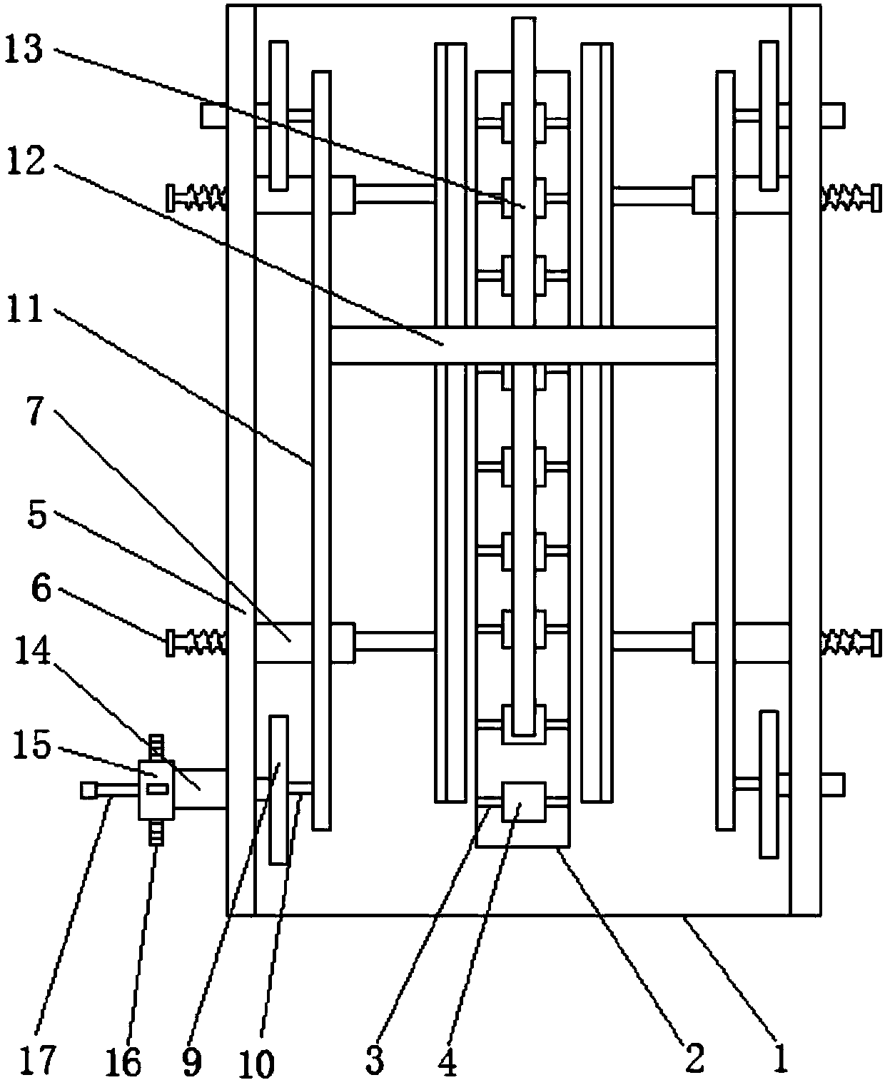
[0022] see Figure 1-4 , a material guide plate structure of a shearing machine, comprising a bottom plate 1, a notch 2 is provided in the middle of the top of the bottom plate 1, a positioning shaft 3 on the bottom plate 1 is fixedly fitted on the top of the notch 2, and a middle part of the positioning shaft 3 is movable. There are guide rollers 4, the number of guide rollers 4 is nine, and the nine guide rollers 4 are equidistantly arranged in the notch 2, ...


PUM


Abstract

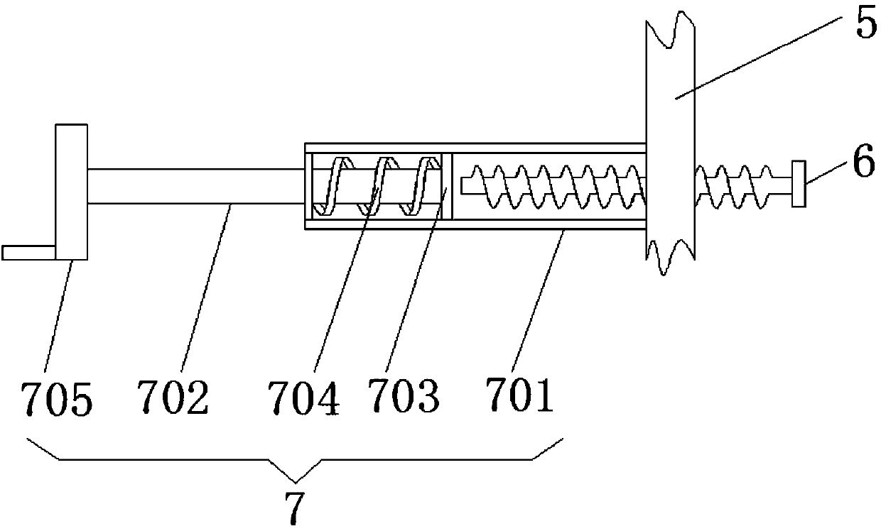
The invention relates to the technical field of shearing machines, and discloses a material guide plate structure of a shearing machine, comprising a bottom plate, a notch is opened in the middle of the top of the bottom plate, and the top of the notch is fixedly fitted with a positioning plate located on the bottom plate. shaft, the middle movable sleeve of the positioning shaft is equipped with guide rollers, side plates are fixedly installed on both sides of the top of the bottom plate, and threaded rods are threaded on the sides of the two side plates. The number is four, and each group of two threaded rods is respectively distributed on the side surfaces of the two side plates, and one end of the threaded rods extends to the inside of the limiting device. The material guide plate structure of the shearing machine drives the turntable to rotate through the ratchet, so that the pressing plate moves down to flatten the raised thinner metal sheet, thus solving the problem of protrusion when cutting and positioning the thinner metal sheet, and is easy to operate The personnel cuts the thinner sheet metal, thereby improving the cutting efficiency of the sheet metal.

Description

technical field [0001] The invention relates to the technical field of shearing machines, in particular to a material guide plate structure of a shearing machine. Background technique [0002] Shearing machines are widely used in modern metal manufacturing industry, and are widely used in aviation, light industry, metallurgy, chemical industry, construction, shipbuilding, automobile, electric power, electrical appliances, decoration and other industries to provide special machinery and complete sets of equipment. When using a shearing machine, the sheet metal is positioned to obtain the required shear size when the sheet metal is being cut. When the sheet metal is positioned, the thinner sheet metal will be raised, so that the sheet metal It is inconvenient to cut, which brings trouble to the operator, thereby reducing the shearing efficiency of the metal sheet, thereby reducing the practicability of the shearing machine. Contents of the invention [0003] (1) Solved tech...

Claims


Application Information

Patent Timeline
Patent Type & Authority Applications(China)
IPC IPC(8): B23D33/02
CPCB23D33/02
Inventor 陈党照
Owner 陈党照
Learn More