Building structure of aluminum mold beam side plate above architectural door opening

A technology of aluminum formwork and aluminum formwork, which is applied in building construction, formwork/formwork components, and on-site preparation of building components, etc., can solve the problems of increased construction cost, large environmental impact of waste, and low overall construction efficiency. Achieve the effect of avoiding delays in the construction period, high construction efficiency, and preventing environmental damage

Active Publication Date: 2018-03-20
CHINA MCC5 GROUP CORP
View PDF5 Cites 5 Cited by
  • Summary
  • Abstract
  • Description
  • Claims
  • Application Information

AI Technical Summary

Problems solved by technology

[0004] In order to solve the above-mentioned technical problems, the present invention provides an aluminum formwork girder side plate erecting structure above the building doorway to effectively reduce the labor, cost and construction period losses caused by architectural design changes, greatly improve the construction efficiency and strengthen the aluminum formwork. The purpose of overall stability and bearing capacity is to solve the problem of using temporary wooden templates instead of temporary wooden templates after size changes or returning to the factory for redesign, resulting in extended construction period, increased construction costs, greater impact of waste on the environment, and poor versatility. And the problem of low overall construction efficiency

Method used


Image

  • Building structure of aluminum mold beam side plate above architectural door opening
  • Building structure of aluminum mold beam side plate above architectural door opening

Examples


Embodiment Construction

[0021] The present invention will be described in further detail below in conjunction with specific embodiments. The purpose of the following words is to illustrate the present invention, rather than limit the protection scope of the present invention.

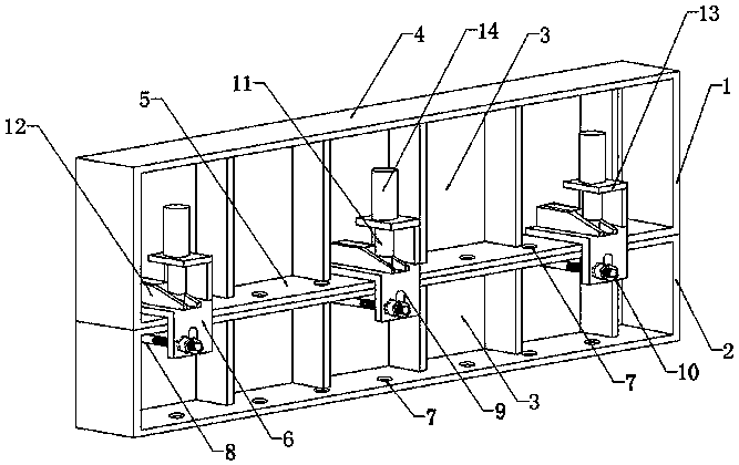
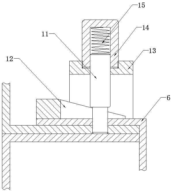
[0022] Such as figure 1 , figure 2 As shown, the present invention can be implemented in the following manner, a structure for erecting aluminum formwork beam side plates above a building doorway, comprising at least two aluminum formworks spliced ​​up and down (this embodiment provides two conventional aluminum formworks, the heights of which are respectively 200mm and 150mm, that is, the upper 200mm aluminum formwork 1 and the lower 150mm aluminum formwork 2), each aluminum formwork is arranged in sequence along the same direction and is spliced ​​up and down. The aluminum mold upper edge plate 4 and the aluminum mold lower edge plate 5 on the upper side and the lower side of the mold side beam plate 3, and the upper edge ...


PUM

PropertyMeasurementUnit
thicknessaaaaaaaaaa

Abstract

The invention relates to the technical field of architectural construction, and discloses a building structure of an aluminum mold beam side plate above an architectural door opening. The structure comprises at least two aluminum mold plates vertically jointed; the aluminum mold plates comprise aluminum mold side beam plates, aluminum mold upper edge plates and aluminum mold lower edge plates; thealuminum mold plates further comprise a plurality of aluminum mold fastening sheets, and a plurality of evenly distributed aluminum mold pin holes are formed in the aluminum mold lower edge plates; at least two aluminum mold connecting bolts are connected with the surfaces of the aluminum mold side beam plates; the aluminum mold fastening sheets are of L-shaped structures, and strip sliding groove holes with which the aluminum mold connecting bolts can be sleeved are formed in one supporting arm, and fastening pin holes matched with the aluminum mold pin holes are formed in the other arm, thefastening pin holes are movably sleeved with ladder pins, and the ladder pins are matched with automatic locking mechanisms which drive the ladder pins to ascend and descend. The problems of prolonged construction periods, increased construction costs, poor universality, and lower overall construction efficiency caused by construction site size changing in the prior art are solved.

Description

technical field [0001] The invention relates to the technical field of building construction, in particular to a structure for erecting side plates of aluminum formwork beams above building door openings. Background technique [0002] Aluminum formwork is a building formwork made of aluminum alloy. Because of its advantages over traditional building wood formwork, it has been widely used in the construction industry. The components of the aluminum formwork system need to be designed and processed according to the characteristics of the floor. The formwork size is accurate and difficult to change, but the construction site is changing, and there are often design changes such as door opening size changes and beam height changes. Generally, processing temporary wood The formwork replaces the aluminum formwork for construction or returns to the factory to redesign and process a complete set of aluminum formwork according to the changed data. [0003] If the construction metho...

Claims


Application Information

Patent Timeline
Patent Type & Authority Applications(China)
IPC IPC(8): E04G9/06E04G13/04E04G17/04
Inventor 梁茂谢锦鸿陈磊
Owner CHINA MCC5 GROUP CORP
Why Eureka
Try Eureka