Safe and stable type platform canopy station building and mounting method thereof

A safe and stable canopy technology, applied in the field of construction manufacturing, can solve the problems of relatively serious external conditions, increased construction volume, and lack of popularization, so as to reduce construction workload, improve safety, and ensure demand and quality. Effect

Active Publication Date: 2018-03-20
JIANGSU HUNING STEEL MECHANISM
View PDF13 Cites 8 Cited by
  • Summary
  • Abstract
  • Description
  • Claims
  • Application Information

AI Technical Summary

Problems solved by technology

The same is true for the construction industry. With the emergence of high-speed trains, high-speed rails, and subways, each station needs a platform. At present, most buildings are constructed of reinforced concrete. However, due to the particularity of construction, the weather and external conditions The requirements are more serious, thus promoting the emergence of steel structure buildings
[0003] However, the existing steel structure buildings are still only in some large venues and have not been popularized, especially for some platforms. Most of the existing station buildings are all equipped with platforms, which not only increases the amount of construction, but also It causes a waste of resources, and there are certain safety hazards in its design and later use

Method used


Image

  • Safe and stable type platform canopy station building and mounting method thereof
  • Safe and stable type platform canopy station building and mounting method thereof
  • Safe and stable type platform canopy station building and mounting method thereof

Examples


Embodiment

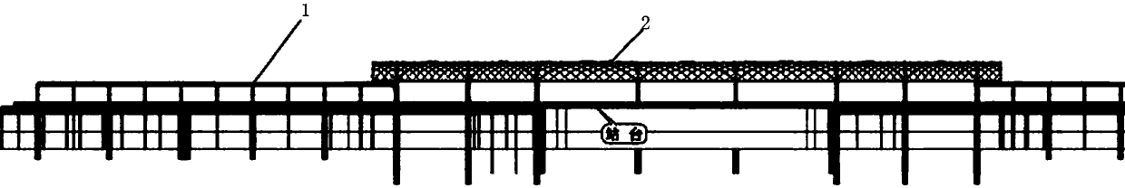
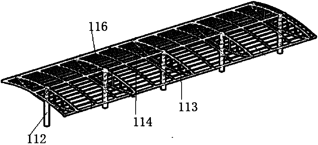
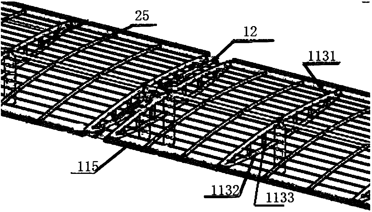
[0064] As shown in the figure, a safe and stable platform canopy station house includes: a platform post canopy 1 and a platform post-free canopy 2, and the platform post canopy 1 is arranged between the platform post-free canopy 2, A group of support structures 11 are arranged in the platform column canopy 1, and a steel column 112, a canopy truss cantilever beam 113, a longitudinal beam member 114, a keel 115 and a connecting beam 116 are arranged in the support structure 111. The canopy truss cantilever beam 113 is arranged on the steel column 112, the longitudinal beam member 114 is longitudinally arranged between the steel columns 112, and passes on the canopy truss cantilever beam 113, and the keel 115 is arranged on the canopy At both ends of the truss cantilever beam 113, a steel beam 25 is arranged between the two keels 115. The steel beam 25 is arranged in the longitudinal beam member 114, and its two ends are connected with the keel 115. The connecting beam 116 is ho...

Embodiment 2

[0073] As shown in the figure, a safe and stable platform canopy station house includes: a platform post canopy 1 and a platform post-free canopy 2, and the platform post canopy 1 is arranged between the platform post-free canopy 2, A group of support structures 11 are arranged in the platform column canopy 1, and a steel column 112, a canopy truss cantilever beam 113, a longitudinal beam member 114, a keel 115 and a connecting beam 116 are arranged in the support structure 111. The canopy truss cantilever beam 113 is arranged on the steel column 112, the longitudinal beam member 114 is longitudinally arranged between the steel columns 112, and passes on the canopy truss cantilever beam 113, and the keel 115 is arranged on the canopy At both ends of the truss cantilever beam 113, a steel beam 25 is arranged between the two keels 115. The steel beam 25 is arranged in the longitudinal beam member 114, and its two ends are connected with the keel 115. The connecting beam 116 is ho...

Embodiment 3

[0110] As shown in the figure, a safe and stable platform canopy station house includes: a platform post canopy 1 and a platform post-free canopy 2, and the platform post canopy 1 is arranged between the platform post-free canopy 2, A group of support structures 11 are arranged in the platform column canopy 1, and a steel column 112, a canopy truss cantilever beam 113, a longitudinal beam member 114, a keel 115 and a connecting beam 116 are arranged in the support structure 111. The canopy truss cantilever beam 113 is arranged on the steel column 112, the longitudinal beam member 114 is longitudinally arranged between the steel columns 112, and passes on the canopy truss cantilever beam 113, and the keel 115 is arranged on the canopy At both ends of the truss cantilever beam 113, a steel beam 25 is arranged between the two keels 115. The steel beam 25 is arranged in the longitudinal beam member 114, and its two ends are connected with the keel 115. The connecting beam 116 is ho...


PUM


Abstract

The invention discloses a safe and stable type platform canopy station building. The safe and stable type platform canopy station building comprises a platform pole canopy and platform-pole-free canopies, wherein the platform pole canopy is arranged between the platform-pole-free canopies, a group of supporting structures are arranged in the platform pole canopy, a steel column, a canopy truss cantilever beam, a longitudinal beam component, a keel and a connection beam are arranged in the supporting structures, and a deformation joint is formed between the supporting structures; a supporting system and a reticulated shell system are arranged in the platform-pole-free canopies, the reticulated shell system is arranged on the supporting structures, a main rod piece and a net shed are arranged in the reticulated shell system, and the main rod piece is provided with a peripheral main rod and an inclined main rod. The safe and stable type platform canopy station building disclosed by the invention has the advantages that resource integration is realized by virtue of matched design of the platform pole canopy and the platform-pole-free canopies, the construction workload is effectively reduced and the construction difficulty is reduced simultaneously when demand and quality of the safe and stable type platform canopy station building are guaranteed, the design of the safe and stabletype platform canopy station building is more reasonable, and the demand of people can be better met.

Description

technical field [0001] The invention belongs to the field of building manufacturing, and in particular relates to a safe and stable platform canopy station building. Background technique [0002] With the rapid development of social economy, people's quality of life and living standards are constantly improving, and both the production of enterprises and the pace of people's life are constantly accelerating. The same is true for the construction industry. With the emergence of high-speed trains, high-speed rails, and subways, each station needs a platform. At present, most buildings are constructed of reinforced concrete. However, due to the particularity of construction, the weather and external conditions The requirements are more serious, thus promoting the production of steel structure buildings. [0003] However, the existing steel structure buildings are still only in some large venues and have not been popularized, especially for some platforms. Most of the existing ...

Claims


Application Information

Patent Timeline
Patent Type & Authority Applications(China)
IPC IPC(8): E04H1/12E04B7/10E04G1/15E04G1/36
CPCE04B7/105E04G1/15E04G1/152E04G1/36E04H1/1205E04H1/1211Y02A40/25
Inventor 邵宝健甘国军朱克进巫明杰张伟张广敏肖攀
Owner JIANGSU HUNING STEEL MECHANISM
Why Eureka
Try Eureka