Exhaust system heat shield for supercharged engine

A supercharged engine and exhaust system technology, applied in the direction of engine components, machines/engines, exhaust devices, etc., can solve the problem of large heat load of heat shield, low usage rate of cold air in supercharged, and ineffective isolation Problems such as high-temperature radiation of the engine, to achieve the effect of increasing the utilization rate and improving the utilization rate

Active Publication Date: 2018-03-20
CHONGQING CHANGAN AUTOMOBILE CO LTD
View PDF7 Cites 4 Cited by
  • Summary
  • Abstract
  • Description
  • Claims
  • Application Information

AI Technical Summary

Problems solved by technology

This kind of heat shield only prevents the heat from spreading from the hot end area of ​​the exhaust system to the other side of the heat shield, and does not dissipate heat radiation energy, which will cause the temperature between the exhaust system and the heat shield to rise. The heat load of the cover is relatively large, which cannot effectively block the external high-temperature radiation when the engine is working; and when the engine is working at a high load for a long time, the exhaust manifold, supercharger and catalytic converter in the hot end area of ​​the exhaust system will be damaged. May be overloaded with excess hot air
[0004] Additionally, if figure 1 As shown, in a supercharged engine, the air is supplied to the throttle valve 3 after passing through the air filter 5, the supercharger 6 and the intercooler 2. The air at the outlet of the compressor compressor will continue to flow out. In order to avoid the surge phenomenon of the supercharger compressor caused by the sudden closing of the throttle valve, an air release valve 4 is installed on the pipeline between the intercooler 2 and the throttle valve 3. Under the premise of the demand of valve 3, the air release port of the air release valve 4 returns the excess supercharged intercooled air to the inlet of the supercharger compressor for recharging, and the usage rate of the supercharged intercooled air is not high; and in some engines Under working conditions, the wastegate valve of the supercharger will be opened, and the waste heat energy of the exhaust gas will not be fully utilized.

Method used


Image

  • Exhaust system heat shield for supercharged engine
  • Exhaust system heat shield for supercharged engine
  • Exhaust system heat shield for supercharged engine

Examples


Embodiment Construction

[0021] The present invention will be described in detail below in conjunction with the accompanying drawings.

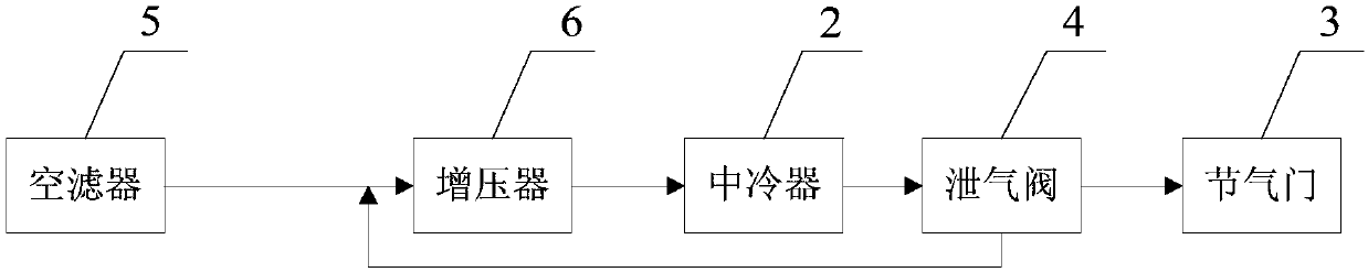
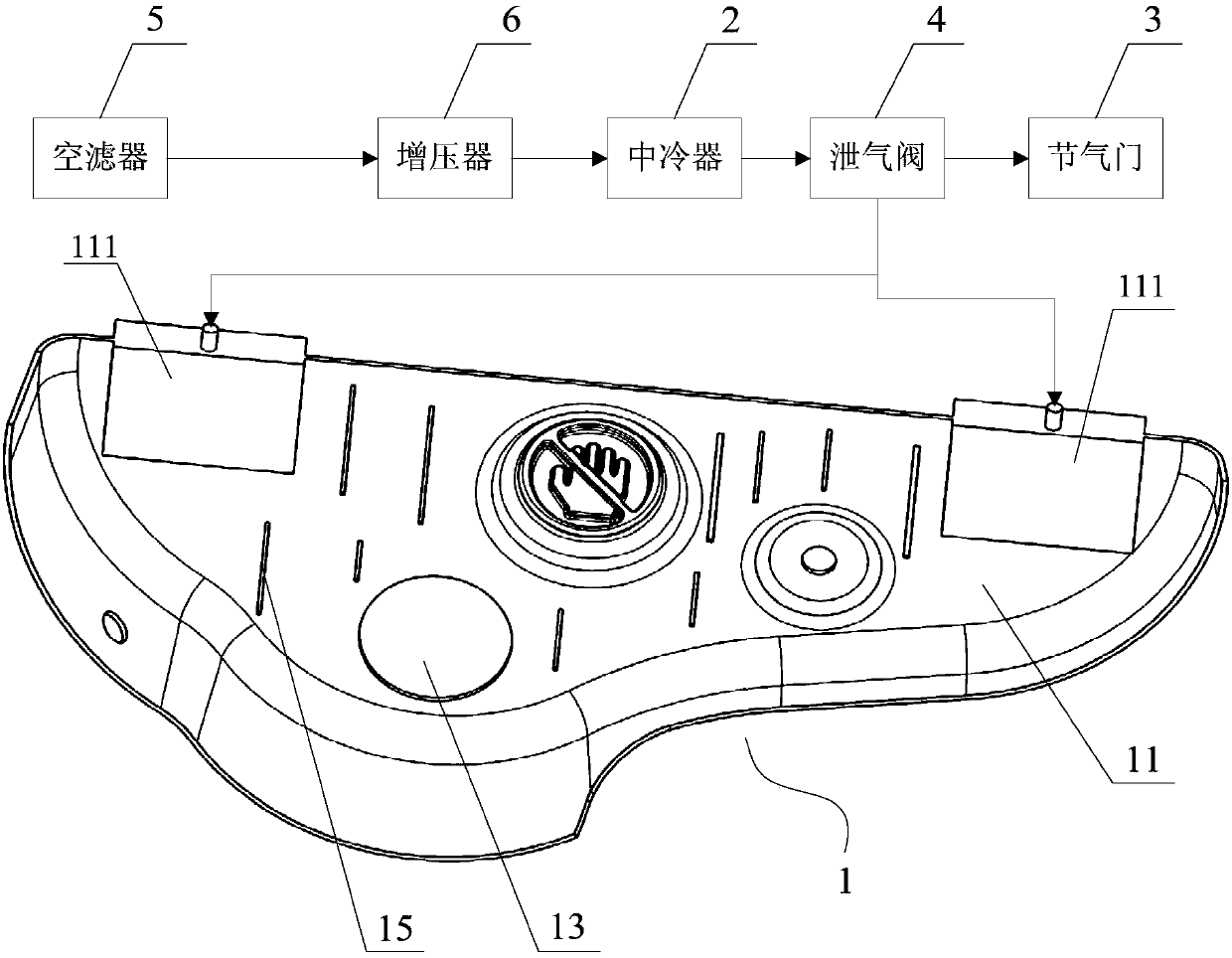
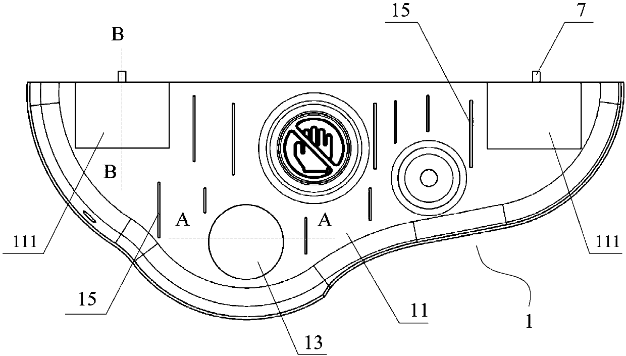
[0022] Such as Figure 2 to Figure 5 The heat shield of the exhaust system of the supercharged engine shown includes a heat shield body 1, and the heat shield body 1 is provided with a vent 13 for the hot air in the hot end area of ​​the exhaust system to escape; the heat shield body 1 includes a first heat shield 11 close to the hot end of the exhaust system and a second heat shield 12 away from the hot end of the exhaust system. The left and right parts of the front side of the first heat shield 11 have a groove 111 respectively, The front left and right parts of the heat insulation board 12 respectively have a protrusion 121 corresponding to the groove 111, the edge of the first heat insulation board 11 is welded and sealed with the edge of the second heat insulation board 12, and an air flow cavity 14 is formed in the middle , the air storage cavity 10 is formed...


PUM


Abstract

The invention discloses an exhaust system heat shield for a supercharged engine. The exhaust system heat shield comprises a heat shield body in which an air vent formed to vent hot air in a hot end region of the exhaust system; the heat shield body is provided with an air storage chamber and an air flow chamber inside, an air inlet of the air storage chamber is connected to an air outlet of an airleakage valve through a pipeline, the air storage chamber is communicated with the air flow chamber, and a plurality of air vent holes communicating the air flow chamber with the hot end region of the exhaust system are formed in the side wall of the air flow chamber near the hot end of the exhaust system. The heat shield insulates the exhaust system, utilizes pressurized intercooled air to coolthe exhaust system and then dissipate heat.

Description

technical field [0001] The invention relates to automobile engine components, in particular to a heat shield for an exhaust system of a supercharged engine. Background technique [0002] When the engine is running normally, the high-temperature exhaust gas formed after its combustion and work is discharged through the exhaust manifold. These high-temperature exhaust gases carry a lot of heat, so the temperature of the exhaust system is relatively high, and it radiates high-temperature heat to the surrounding parts. With the wide application of engine supercharging technology, supercharging engines generally have the advantages of stronger power and more fuel-efficient than naturally aspirated engines, but after adopting supercharging technology, the exhaust gas temperature rises sharply and the heat emitted will also increase accordingly. Therefore, in order to ensure the normal operation and safety of the engine, engineers use the exhaust system heat shield to isolate the e...

Claims


Application Information

Patent Timeline
Patent Type & Authority Applications(China)
IPC IPC(8): F01N13/14
CPCF01N13/14
Inventor 向世建赵艳涛李元颖陈生超
Owner CHONGQING CHANGAN AUTOMOBILE CO LTD
Why Eureka
Try Eureka