Vibrating diaphragm and vibrating diaphragm manufacturing method

A diaphragm production and thin-film technology, which is applied in the field of loudspeakers, can solve the problems of high cost, high difficulty, and low efficiency, and achieve the effects of reducing production costs, easy operation, and reducing defective rates

Inactive Publication Date: 2018-03-20
JIANGSU YUCHENG ELECTRONICS
View PDF4 Cites 4 Cited by
  • Summary
  • Abstract
  • Description
  • Claims
  • Application Information

AI Technical Summary

Problems solved by technology

[0007] The purpose of the present invention is to provide a diaphragm to solve the problems of low efficiency, high difficulty and high cost in the prior art when cutting the outer diameter of the diaphragm and assembling on the production line.
[0008] Another object of the present invention is to provide a diaphragm manufacturing method to solve the problems of low efficiency, high difficulty and high cost in the prior art when cutting the outer diameter of the diaphragm and assembling the production line.

Method used


Image

  • Vibrating diaphragm and vibrating diaphragm manufacturing method
  • Vibrating diaphragm and vibrating diaphragm manufacturing method
  • Vibrating diaphragm and vibrating diaphragm manufacturing method

Examples


no. 1 example

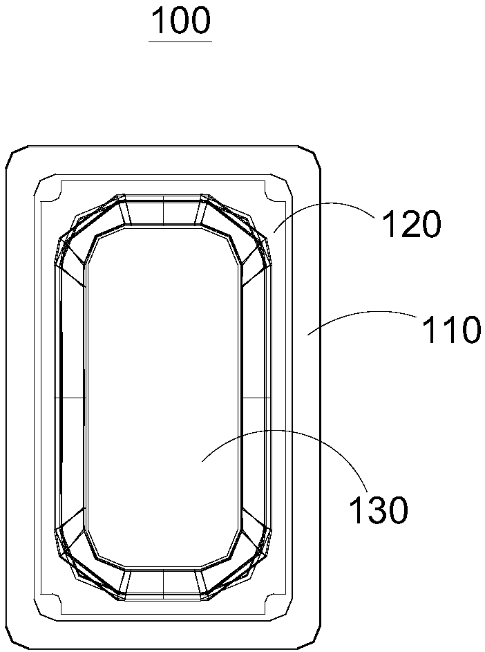
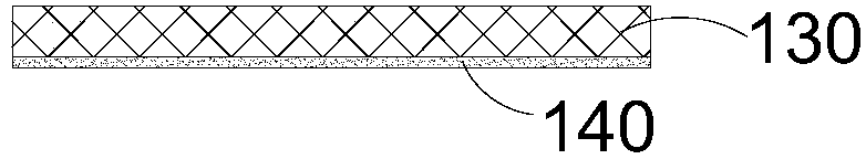
[0038] see figure 1 , the embodiment of the present invention provides a diaphragm 100 , the diaphragm 100 includes a frame 110 , a dome 130 and a film 120 , the edges of the film 120 are connected to the frame 110 , and the film 120 is connected to the dome 130 .

[0039] Specifically, in this embodiment, as the sounding unit of the speaker, the thin film 120 must be thin and soft, so that when the speaker is about to make sound, the dome 130 and the diaphragm 100 vibrate simultaneously, and then the sound is emitted. Due to the soft characteristics of the thin film 120, during the processing of the diaphragm 100, when the outer diameter of the diaphragm 100 is cut (i.e. cutting off the excess thin film 120), the prior art utilizes a cold stamping die or a knife die for cutting. It is more difficult. At the same time, during installation, the assembly between the soft film 120 and the loudspeaker shell is difficult, and because the film 120 is thin, it is easy to be damaged,...

no. 2 example

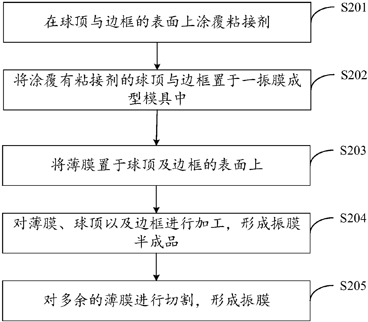
[0051] see Figure 4 , the embodiment of the present invention also provides a diaphragm manufacturing method, the diaphragm manufacturing method includes the following steps:

[0052] Step S201 , coating adhesive on the surface of the dome 130 and the frame 110 .

[0053] In order to realize the connection of the dome 130 , the frame 110 and the film 120 , an adhesive needs to be coated on one side of the dome 130 and the frame 110 to bond the dome 130 , the frame 110 and the film 120 . In this embodiment, thermosetting glue is selected as the adhesive.

[0054] Step S202 , placing the dome 130 and the frame 110 coated with adhesive in a diaphragm forming mold 150 .

[0055] After coating the adhesive on one side of the dome 130 and the frame 110, and drying the surface with the adhesive, the dome 130 and the frame 110 are placed in a diaphragm forming mold 150, and the diaphragm forming mold 150 is provided with The positioning groove, the ball top 130 and the frame 110 a...


PUM


Abstract

The invention provides a vibrating diaphragm and a vibrating diaphragm manufacturing method, and relates to the technical field of loudspeakers. The vibrating diaphragm comprises a frame, a ball top and a thin film. The area enclosed by the frame is larger than the area of the ball top, and the edges of the thin film are all connected with the frame surface, and the thin film is connected with thesurface of the ball top. The vibrating diaphragm and the vibrating diaphragm manufacturing method provided by the invention have the advantages of high efficiency, low difficulty and low cost duringouter diameter cutting of the vibrating diaphragm and production line assembly.

Description

technical field [0001] The invention relates to the technical field of loudspeakers, in particular to a diaphragm and a method for manufacturing the diaphragm. Background technique [0002] With people's continuous pursuit of quality of life, the electronics industry has developed rapidly. As the sound generating devices of various electronic products, such as mobile phones and computer devices, the demand for speakers is increasing day by day. [0003] As the sound unit of the speaker, the performance of the diaphragm directly determines the quality of the speaker. With the continuous development of the industry, the requirements for the speaker are getting higher and higher, and the performance requirements for the diaphragm are also getting higher and higher. , the development trend of the diaphragm material is also turning to the direction of thinner and softer, and the thinner and softer the diaphragm material will bring two problems: [0004] 1. When cutting the oute...

Claims


Application Information

Patent Timeline
Patent Type & Authority Applications(China)
IPC IPC(8): H04R31/00H04R7/12B23K26/38B29C65/48
CPCH04R31/003B23K26/38B29C65/02B29C65/4835B29C66/02241H04R7/127H04R2231/001H04R2307/025H04R2307/027
Inventor 曹飞李祥琴华克
Owner JIANGSU YUCHENG ELECTRONICS
Why Eureka
Try Eureka