Electrically controlled depth-limiting moldboard plow

A plough-type plough and depth-limiting technology, applied in ploughs, agricultural machinery and implements, applications, etc., can solve the problem that the depth-limiting height cannot be changed in time according to the ground conditions, the dynamic adjustment of the depth-limiting depth cannot be realized, and the manual depth-limiting wheel is inconvenient to operate, etc. problems, to achieve the effect of improving farming efficiency, simple structure, and convenient operation of depth limit

Inactive Publication Date: 2018-03-23
成都市宏吉农业有限责任公司
View PDF0 Cites 1 Cited by
  • Summary
  • Abstract
  • Description
  • Claims
  • Application Information

AI Technical Summary

Problems solved by technology

For the soil in different regions, the requirements for the depth of tillage are different. If the depth of tillage is not limited, it will lead to the destruction of the soil structure and the decrease of soil fertility, which will affect the grain yield.
Therefore, the general plow is equipped with a depth-limiting device. For now, this depth-limiting device is mainly a manual depth-limiting wheel. By manually turning the handle, the height of the depth-limiting wheel is adjusted to achieve the purpose of depth-limiting, but this There are many problems in the use of this kind of depth gauge wheel. This kind of manual depth gauge wheel is very inconvenient to operate. It must be adjusted manually according to the ground conditions every time it is used, and it needs a lot of torque to complete when turning the handle. Time-consuming and labor-intensive, the depth limit height cannot be changed in time according to the ground conditions
Every time you adjust the height of the depth-limiting wheel, you must stop tilling and continue after adjusting the height of the depth-limiting wheel. It is impossible to dynamically adjust the depth of the depth-limiting wheel while plowing, which will affect the farming efficiency.

Method used


Image

  • Electrically controlled depth-limiting moldboard plow
  • Electrically controlled depth-limiting moldboard plow

Examples


Embodiment Construction

[0020] The technical solutions of the present invention will be clearly and completely described below in conjunction with the embodiments. Apparently, the described embodiments are only some of the embodiments of the present invention, not all of them. Based on the embodiments of the present invention, all other embodiments obtained by those skilled in the art without making creative efforts belong to the protection scope of the present invention.

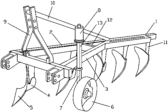
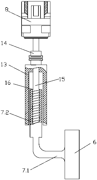
[0021] refer to Figure 1-2 , the present invention provides a technical solution: an electronically controlled depth-limiting conventional plow, including a frame 1, and the frame 1 includes a first arm 2 and a second arm 3, and several A plow share assembly, the second support arm 3 is equipped with a depth-limiting assembly, the depth-limiting assembly includes a depth-limiting wheel 6, an "L"-shaped fixed rod 7, a depth-limiting shaft 15 and a reduction motor 8, and the depth-limiting wheel 6 is movably installed on the "L" O...


PUM


Abstract

The invention discloses an electronically controlled depth-limiting plow. Several plowshare assemblies are suspended on the first support arm (2), the depth-limiting assembly is installed on the second support arm (3), and the depth-limiting wheel (6) is movable. Installed on the foot (7.1) of the "L" type fixed rod (7), the vertical arm (7.2) of the "L" type fixed rod (7) has a deep hole (16) with internal thread, the depth limit The lower part of the shaft (15) is installed in the deep hole (16) through the external thread on it, and the guide cylinder (13) is fixedly installed on the second support arm (3), and the guide cylinder (13) is arranged on the vertical arm (7.2 ), the upper part of the depth-limiting shaft (15) is connected with the output shaft of the geared motor (8) through a coupling (14), and the geared motor (8) is connected with an external electric control device; the present invention adopts an electrically controlled depth-limiting device , The depth limit can be set with one key in the tractor cockpit, which makes the plow depth limit operation more convenient and more accurate, and achieves high-quality soil cultivation effects.

Description

technical field [0001] The invention relates to a conventional plow, in particular to an electronically controlled depth-limiting conventional plow. Background technique [0002] With the development of science and technology, machinery is more and more widely used in agriculture, and agricultural mechanization and automation are the inevitable trend of agricultural development. There are many kinds of agricultural machinery, the common ones are farming machinery, sowing machinery, and harvesting machinery. Cultivation can be divided into deep plowing and shallow plowing. For deep plowing, plow plows are generally used, and the soil is deeply plowed through the sharp blade of plowshares. , dig out the eggs inside the soil, and kill the eggs by sunlight. This kind of conventional plow is hung at the tail of the tractor, and the tractor is pulled to complete the tillage. For the soil in different regions, the requirements for the depth of tillage are different. If the depth o...

Claims


Application Information

Patent Timeline
Patent Type & Authority Applications(China)
IPC IPC(8): A01B3/38
CPCA01B3/38
Inventor 叶启银
Owner 成都市宏吉农业有限责任公司
Why Eureka
Try Eureka