Solvent recovery method

A recovery method and solvent technology, applied in the field of solvent recovery, can solve problems such as the entry of digestive cotton dust, easy mixing into solvents, and lack of management of equipment, achieving high recovery rates and avoiding safety accidents

Inactive Publication Date: 2018-03-23
XINZHONGTIAN ENVIRONMENTAL PROTECTION
View PDF3 Cites 0 Cited by
  • Summary
  • Abstract
  • Description
  • Claims
  • Application Information

AI Technical Summary

Problems solved by technology

[0003] For example, in the process of using nitrocellulose as a raw material to prepare a single-base drug, in order to separate the solvent and recycle it, the prior art generally heats the mixed material and uses an exhaust pipe to extract the solvent vapor, but before and after the single-base drug is formed Part of the digestive cotton dust will always enter the ventilation duct; especially when making small-sized medicines, due to the large air volume or lack of equipment management, some medicine particles will be sucked into the ventilation duct
These dusts are adsorbed on the inner wall of the exhaust pipe, and it is easy to block the exhaust pipe for many years; and in the process of recovering the solvent through negative pressure through the exhaust, it is easy to mix into the solvent, affecting the recovery quality of the solvent

Method used


Image

  • Solvent recovery method

Examples


Embodiment 1

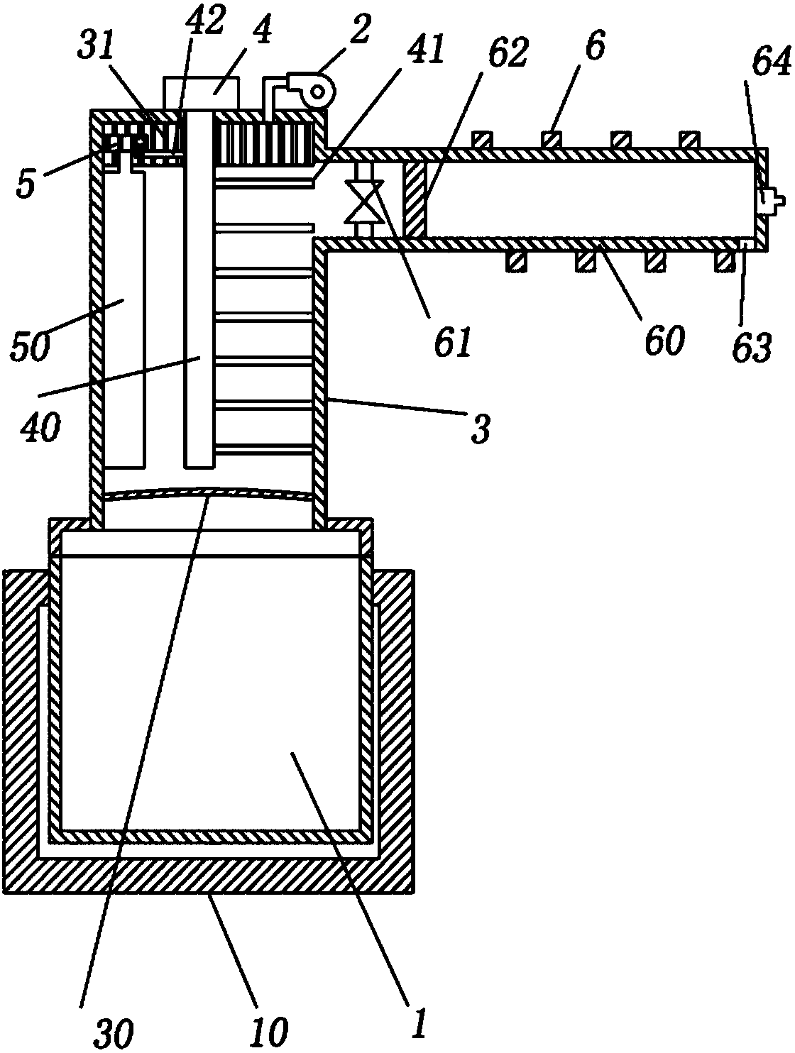
[0027] Embodiment 1 is basically as attached figure 1 Shown, solvent recovery method, comprises the following steps:

[0028] A. Put the mixed material into the reaction tank 1, heat the mixed material, and make the solvent be heated to form steam; the reaction tank 1 includes a tank body and a tank cover that is closed on the top of the tank body; the device for heating the mixed material is preferably an electric heating mantle 10, and the reaction tank The tank body of 1 is embedded in the heater; the electric heating jacket 10 can be used to control the temperature conveniently, so that this equipment can be easily applied to the recovery of solvents with different boiling points, and the operation is simple;

[0029] B, the steam obtained in step A is passed into the dust removal unit; the dust removal unit includes a dust suction fan 2, an exhaust pipe 3, a motor 4, a rotating shaft 40 and a gear 5; the bottom of the exhaust pipe 3 runs through the tank cover of the reac...

Embodiment 2

[0036] The difference between this embodiment and Embodiment 1 is that in step D, the one-way valve 61 is closed every 8 days, the motor 4 and the dust suction fan 2 are started, and the dust removal is performed on the exhaust pipe 3, and the dust removal time is 60s.

Embodiment 3

[0038]The difference between this embodiment and Embodiment 1 is that in step D, the one-way valve 61 is closed every 10 days, the motor 4 and the dust suction fan 2 are started, and the dust removal is carried out on the air duct 3, and the dust removal time is 85s.


PUM


Abstract

The invention relates to the technical field of recovery of vapor, exhaust gas and the like, in particular to a solvent recovery method. The solvent recovery method comprises the following steps: (A)a mixture is poured into a reaction tank, and the mixture is heated, so that a solvent is heated into steam; (B) the steam obtained in step A is injected into a dust removal unit; (C) the steam obtained in step B is injected into a recovery unit, wherein the recovery unit comprises a condensing tube and a recovery pipe communicating with an exhaust column, a check valve, a liquid outlet communicating with a collecting bottle and an adaptor communicating with a vacuum device are arranged on the recovery pipe, and the condensing tube is arranged on the outer wall of the recovery pipe; the checkvalve is opened, the condensing tube is started, and a liquid solvent is collected from the liquid outlet; (D) the check valve is closed once every 5 to 10 days, and a motor and a dust suction fan arestarted to remove dust of the exhaust column. By adopting the technical scheme, dust can be effectively prevented from being mixed into the solvent, moreover, the dust of the exhaust column can be removed, and thereby the quality of the recovered solvent is increased.

Description

technical field [0001] The invention relates to the technical field of recovery of steam, waste gas, etc., in particular to a solvent recovery method. Background technique [0002] In the field of organic chemistry, low-molecular-weight organic solvents are often used to dissolve various types of high-molecular-weight solutes for pre-treatment or post-treatment steps such as preparation and purification. After pre-treatment or post-treatment, it is often necessary to remove the solvent from the solute Remove and recycle to prevent solvent volatilization from affecting the environment. Since most of the solvents are low-molecular-weight organic compounds, they have good volatility. Therefore, in the process of recovering solvents, heating is often used to make a large amount of solvents form steam and volatilize, thereby separating them from the solute. , and recover the solvent. [0003] For example, in the process of using nitrocellulose as a raw material to prepare a sin...

Claims


Application Information

Patent Timeline
Patent Type & Authority Applications(China)
IPC IPC(8): B01D1/00B08B15/04B01D5/00B01D53/26
CPCB01D1/00B01D5/0009B01D53/263B01D2257/80B08B15/04
Inventor 林辉荣阳杨邓波胡懿许桂连汪小飞
Owner XINZHONGTIAN ENVIRONMENTAL PROTECTION
Why Eureka
Try Eureka